RFID (Radio Frequency Identification) antenna deployment system and method used for real-time monitoring of warehouse

A real-time monitoring and deployment system technology, applied in the field of electronic information, can solve the problems that the maximum coverage of RFID antennas cannot be realized, the index constraints of height, position, and angle are not considered, and the impact of reading and writing recognition performance is not considered.

Inactive Publication Date: 2015-04-08
SHANGHAI UNIV
View PDF9 Cites 8 Cited by
  • Summary
  • Abstract
  • Description
  • Claims
  • Application Information

AI Technical Summary

Problems solved by technology

In the paper "Optimized deployment of RFID network based on hybrid particle swarms" published by Liu Kuai et al. in the fourth issue of "Computer Application Research" in 2012, this paper introduces the optimal deployment of RFID antennas in the two-dimensional moment plane. A hybrid particle swarm optimization algorithm is used to optimize the deployment position of the reader, so that the reader can read multiple tag information while reducing the conflict problem, but this deployment method does not consider the impact of the three-dimensional space environment on the read-write recognition performance of the RFID antenna; Liu Yu et al. in the invention patent CN 101872885B "a system and meth...

Method used


Image

  • RFID (Radio Frequency Identification) antenna deployment system and method used for real-time monitoring of warehouse
  • RFID (Radio Frequency Identification) antenna deployment system and method used for real-time monitoring of warehouse
  • RFID (Radio Frequency Identification) antenna deployment system and method used for real-time monitoring of warehouse

Examples


Embodiment Construction

[0043] In order to make the purpose, technical solutions and advantages of the present invention clearer, the present invention will be further elaborated below in combination with specific examples and with reference to the accompanying drawings.

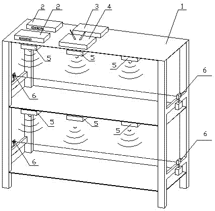
[0044] Such as figure 1 as shown, figure 1 It is a schematic diagram of an RFID antenna deployment system for real-time monitoring of warehouses,

[0045] Including shelf 1, RFID reader 2, GPIO Box conversion control box 3, wireless router 4, RFID antenna 5, photoelectric sensor 6;

[0046] The shelf 1 is a storage shelf with at least two layers of stacked goods for storage, and is used to deploy the RFID reader-writer 2, the GPIO Box conversion control box 3, the wireless router 4, the RFID antenna 5, and the photoelectric sensor 6, wherein,

[0047] The RFID reader-writer 2, the GPIO Box conversion control box 3, and the wireless router 4 are deployed on the top surface of the first shelf of the shelf 1;

[0048] The RFID ante...


PUM


Abstract

The invention discloses a RFID (Radio Frequency Identification) antenna deployment system and method used for the real-time monitoring of a warehouse. The system comprises a goods shelf arranged in the warehouse, RFID reader-writers, RFID antennae, photoelectric sensors, a GPIO (General Purpose Input/Output) box switching control cabinet and a wireless router, wherein the RFID antennae are arranged on the upper side surface of each interlayer frame of the goods shelf at a set dig angle [Beta], and the RFID antennae are connected with the RFID reader-writers through RFID cables. During a test, a product stuck with a RFID label is arranged on a shelf in the middle of each interlayer frame of the goods shelf, and the RFID reader-writers identify the RFID label stuck on the product through the RFID antennae; and according to the deployment functions of the RFID antennae, the deployment function value of each RFID antenna is calculated, the height, the position and the angle of each RFID antenna in each interlayer frame are regulated to obtain an optimal identification energy threshold value, and the energy threshold value is taken as a basis to judge whether each RFID antenna is deployed on an optimal position or not. The RFID antenna optimization deployment of the real-time monitoring of the warehouse is realized, and the signal interference of an adjacent storage location is lowered.

Description

technical field [0001] The invention relates to the field of electronic information technology, in particular to an RFID antenna deployment system and method for real-time monitoring of warehouses. Background technique [0002] With the rapid development of information science, RFID (Radio Frequency Identification) technology in the Internet of Things, that is, radio frequency identification technology, has been widely used in many fields such as manufacturing supply chain logistics, manufacturing and traffic management. Since different types of products have different placement forms and quantities when they pass through the RFID identification range, and the electromagnetic environment and space around the gate where the RFID antenna is deployed are also different, it is difficult to find an optimal RFID antenna deployment method, the optimal RFID antenna The deployed application environment requires comprehensive optimization of the RFID reader antenna height, antenna pos...

Claims


Application Information

Patent Timeline
IPC IPC(8): G06K17/00G06K19/07G06Q10/08G06Q50/28
Inventor 刘丽兰袁自龙晋彦磊陈诚刘雪伟
Owner SHANGHAI UNIV
Why Eureka
Try Eureka