A dual circularly polarized microstrip antenna array
What is AI technical title?
AI technical title is built by Patsnap AI team. It summarizes the technical point description of the patent document.
A microstrip antenna, dual circularly polarized technology, applied in different polarization directions of antenna unit combinations, antennas, radiating element structures, etc. High performance, compact structure, good for confidentiality
Active Publication Date: 2017-04-19
CHINA ELECTRONIC TECH GRP CORP NO 38 RES INST
View PDF5 Cites 0 Cited by
Summary
Abstract
Description
Claims
Application Information
AI Technical Summary
This helps you quickly interpret patents by identifying the three key elements:
Problems solved by technology
Method used
Benefits of technology
Problems solved by technology
The disadvantage is that the feed network is complex, huge and costly
Method used
Image
Click on the blue label to locate the original text in one second.
Reading with bidirectional positioning of images and text.
Examples
Embodiment 1
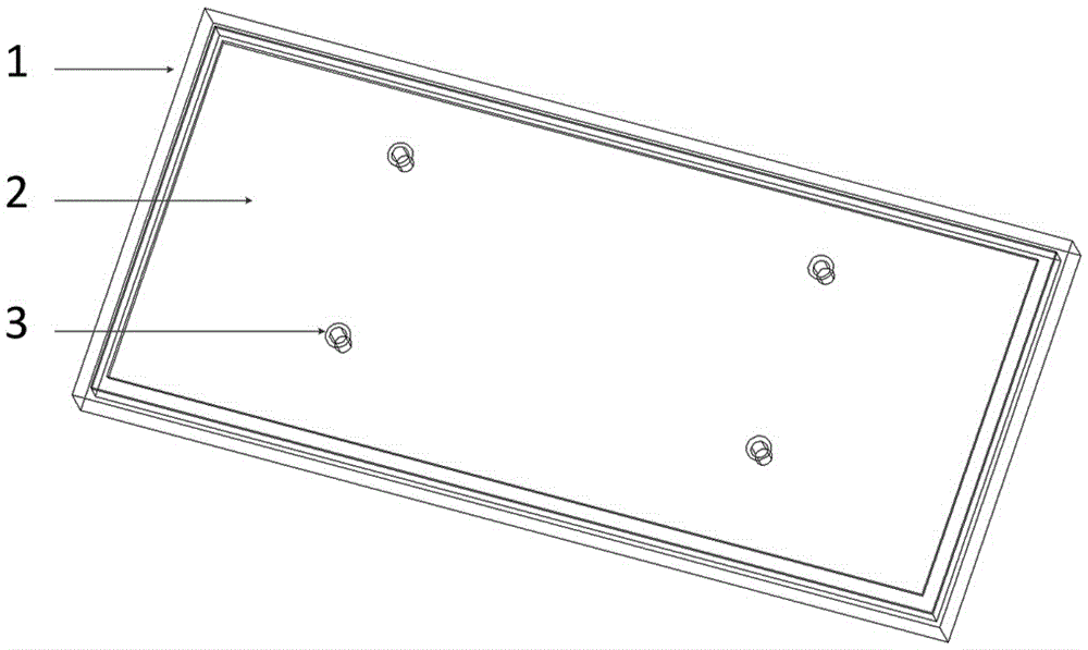
[0040] see figure 1 with figure 2 , a basic 4 (non-scanning) x 2 (scanning) antenna array. The pitch of the patches is determined by a conventional array antenna design method well known in the industry according to scanning requirements. In embodiment 1, the non-scanning direction unit spacing is selected as 0.59λ 0 , the scanning element spacing is selected as 0.52λ 0 . where λ 0 is the free-space wavelength.
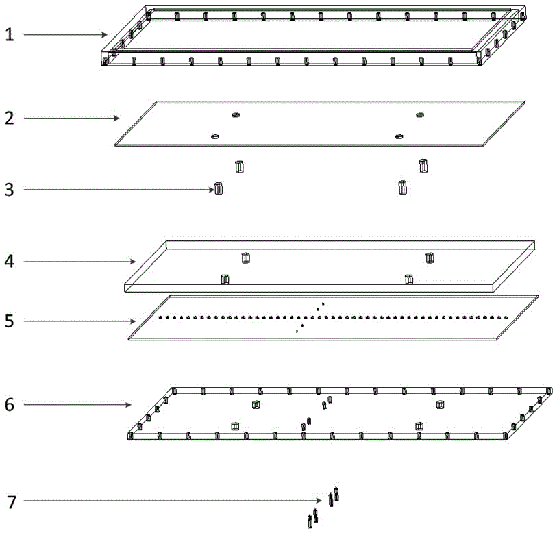
[0041] The antenna array is structurally composed of a metal frame 1 , a radiating microstrip board 2 , a metal post 3 , a foam board 4 , a feeding microstrip board 5 , a metal floor 6 and a connector 7 .
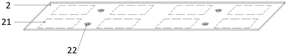
[0042] Such as image 3 As shown, the upper surface of the radiating microstrip board 2 has four symmetrical pads 22 arranged uniformly front and back, and the lower surface has eight radiation patches 21 evenly arranged in 4 rows and 2 columns. Four through holes are penetrated in the up and down direction.
[0043] Such as Figure 4 As shown, the foam ...
Embodiment 2
[0050] see Figure 8 , a dual circularly polarized antenna array with 4 (non-scanning)×3 (scanning) elements, the other structures are the same as in Embodiment 1, and the same element spacing is used, the difference lies in the number of antenna elements.
[0051] Figure 9 The measured curves of the standing wave at the two circularly polarized ports of the antenna of embodiment 2 are given, which shows that the standing wave at the port of the antenna array is better than 1.6 in the working frequency band with a relative bandwidth of about 9%.
[0052] Figure 10 with Figure 11 The test results of the typical lobe pattern of the intermediate frequency in Example 2 are given. The normal cross-polarization of the antenna array is better than -15dB in the whole working frequency band.
Embodiment 3
[0054] see Figure 12 , a dual circularly polarized antenna array with 8 (non-scanning direction)×4 (scanning direction) units, the other structures are the same as in Embodiment 1, the difference lies in the number of antenna units, and the antenna units use circular microstrip patch units. The non-scanning element spacing is selected as 0.6λ 0 , the scanning element spacing is selected as 0.8λ 0 . The antenna array is simulated using the industry-recognized HFSS11.0 (high-frequency structure simulation software developed by Ansoft). -15dB.
PUM
Abstract
The invention discloses a dual-circular polarization microstrip antenna array which comprises a metal frame, a radiation microstrip board, metal columns, foam, a feeder microstrip board, a metal floor and connectors. Directional couplers, power dividers, radiation patches and isolation hole arrays are integrated by the feeder microstrip board, so that dual-circular polarization radiation functions can be realized. Impedance matching and bandwidth broadening functions can be realized by the radiation microstrip board and a foam board. The connectors are used as interfaces of the dual-circular polarization microstrip antenna array and feeder line systems. Grounding and protection effects can be realized by a frame which comprises the metal frame and the metal floor. Interlayer positioning, structure strengthening and resonant effect eliminating functions can be realized by the metal columns. The dual-circular polarization microstrip antenna array has the advantages that double-layer microstrip patch antennas, circular polarization power division feeder, positioning and supporting, resonance eliminating, mutual coupling isolation and environmental protection technologies are combined with one another, accordingly, merits of low profiles, costs and cross polarization of the traditional circular polarization microstrip patch antennas are inherited, and the dual-circular polarization microstrip antenna array is simple and firm in structure and convenient to process and can be used as a communication or radar dual-circular polarization phased-array antenna.
Description
technical field [0001] The invention belongs to the technical field of antennas, and in particular relates to a microstrip antenna array. Background technique [0002] For satellite communication and remote sensing systems, in order to effectively transmit information and overcome the polarization distortion caused by the ionospheric Faraday rotation effect, the antenna is required to have circular polarization performance, and the same antenna array works simultaneously in the receiving mode and the transmitting mode. This requires the antenna to have the ability to work with dual circular polarization. In terms of military use, in the field of early warning of space targets, countries generally use dual circularly polarized antennas as the basic radiation unit array. In terms of civilian use, the use of dual circularly polarized antennas in radio and television systems can also effectively reduce signal loss and overcome ghosting. This also promotes the development of du...
Claims
Application Information
Patent Timeline
Application Date:The date an application was filed.
Publication Date:The date a patent or application was officially published.
First Publication Date:The earliest publication date of a patent with the same application number.
Issue Date:Publication date of the patent grant document.
PCT Entry Date:The Entry date of PCT National Phase.
Estimated Expiry Date:The statutory expiry date of a patent right according to the Patent Law, and it is the longest term of protection that the patent right can achieve without the termination of the patent right due to other reasons(Term extension factor has been taken into account ).
Invalid Date:Actual expiry date is based on effective date or publication date of legal transaction data of invalid patent.
Patent Type & AuthorityPatents(China)
IPC IPC(8): H01Q1/38H01Q21/24H01Q13/08
Inventor高初李景峰董好志王远
OwnerCHINA ELECTRONIC TECH GRP CORP NO 38 RES INST

