
Eddy current loss-free magnetic separator

A magnetic separation, no eddy current technology, used in magnetic separation, solid separation, chemical instruments and methods, etc., can solve the problems of short service life, easy damage to equipment, easy wear and tear of cylinder skin, etc., to achieve long service life, improve processing quantity, prolonging the service life

Inactive Publication Date: 2015-04-15
LIAONING WUHUAN ENG TECH
View PDF12 Cites 9 Cited by
  • Summary
  • Abstract
  • Description
  • Claims
  • Application Information

AI Technical Summary

Problems solved by technology

[0003] The purpose of the present invention is to provide a high-efficiency, energy-saving and large-capacity magnetic separator without eddy current loss, which solves the problems of the existing magnetic separator, such as the easy wear of the barrel skin, the short service life caused by the heating of the barrel, and the easy damage of the equipment.

Method used


Image

  • Eddy current loss-free magnetic separator
  • Eddy current loss-free magnetic separator
  • Eddy current loss-free magnetic separator

Examples


Embodiment Construction

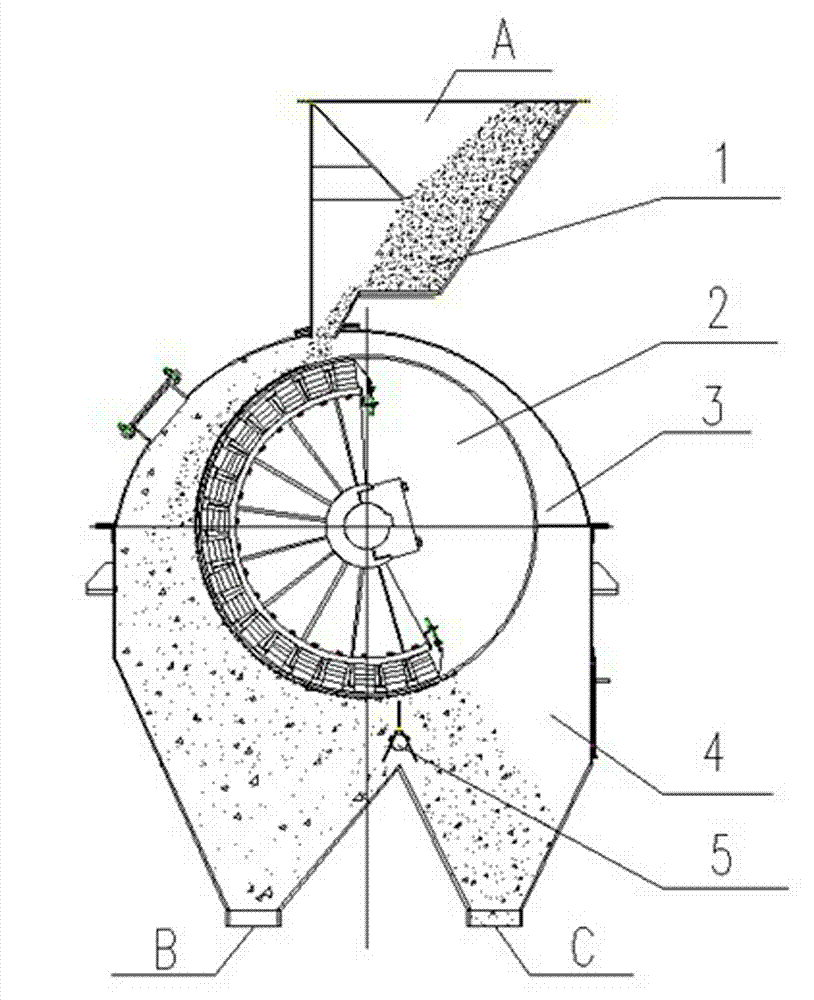
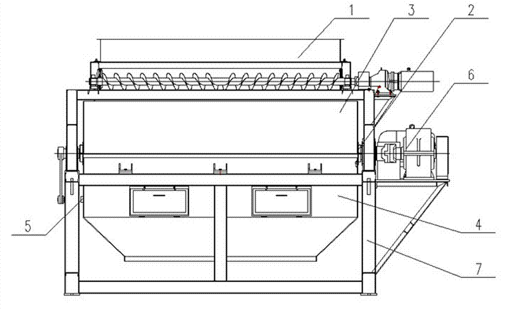
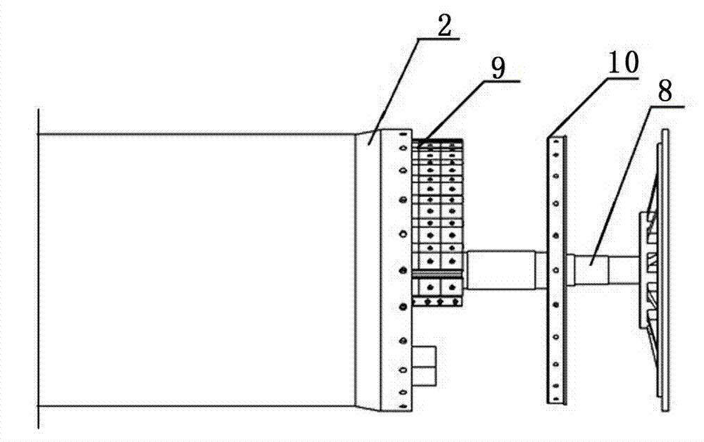
[0015] according to Figure 1~4 The specific structure of the present invention will be described in detail. The magnetic separator without eddy current loss includes an upper box body 3, a lower box body 4, a permanent magnet cylinder body 2, a material distribution device 5 and a drive motor 6 for driving the permanent magnet cylinder body 2, etc. components. Wherein, the upper box body 3 is an arc-shaped structure, and the top of the arc-shaped structure is provided with a distributing device 1 , and a distributing roller is arranged in the distributing device 1 . The bottom of the lower box body 4 is a W-shaped structure, one of the feet of the W-shaped structure is the tailings port B, and the other foot is the concentrate port C. There is a permanent magnet cylinder 2 between the upper box 3 and the lower box 4. The permanent magnet cylinder 2 is provided with a main shaft 8 connected to the output end of the drive motor 6. The two ends of the main shaft 8 are limited ...


PUM


Abstract

The invention relates to an eddy current loss-free magnetic separator, which comprises a feed inlet equipped upper box, a lower box, a permanent magnetic cylinder, a material separator, and a drive motor. The technical key points of the invention lie in that: the permanent magnetic cylinder is made of glass fiber reinforced plastics, the bottom of the lower box is a W-shaped structure, two feet of the W-shaped structure are a tailing port and a concentrate port respectively, the permanent magnetic cylinder is disposed between the upper box and the lower box, and the lower part of the permanent magnetic cylinder is provided with the material separator between the tailing port and the concentrate port; a main shaft is limited in the permanent magnetic cylinder and is provided with a magnetic system not rotating along with the permanent magnetic cylinder, the main shaft is provided with a fixation ring, the end of the permanent magnetic cylinder is mounted on the fixation ring, and the main shaft in the permanent magnetic cylinder is connected to the output shaft of the drive motor; and the top of the upper box is provided with a distribution device corresponding to the feed inlet. The magnetic separator provided by the invention solves the problems of short service life, easy equipment damage and the like caused by easy wear of cylinder skin and cylinder heating in existing magnetic separators, and has the advantages of long service life, simple operation, large treatment capacity, small power consumption, and low maintenance cost, etc.

Description

technical field [0001] The invention relates to mineral processing equipment, in particular to a high-efficiency, energy-saving and large-capacity magnetic separator without eddy current loss. Background technique [0002] The permanent magnetic dry separator has the characteristics of simple structure, low operating cost, large-particle mineral separation, energy saving and environmental protection, and is widely used in the mineral processing industry. However, the average lifespan of ordinary dry separators is 3 to 6 years. Under harsh working conditions, some products have a lifespan of less than a few months, and the wear and heating of the barrel skin are the main causes of failure. The wear of the shell is mainly caused by the sliding between the iron ore particles and the shell. Once the shell is broken, the ore particles will enter the shell and be adsorbed on the surface of the magnetic system, resulting in the lock of the shell. If the ore enters the bearing, it ...

Claims


Application Information

Patent Timeline
IPC IPC(8): B03C1/14
Inventor 张宪伟丁球科张俊飞张喜李嘉
Owner LIAONING WUHUAN ENG TECH
Learn More