Al technical title is built by PatSnap Al team. It summarizes the technical point description of the patent document.
A technology for cleaning equipment and steel balls, which is applied to drying, drying machines, lighting and heating equipment, etc., which can solve the problems of high labor intensity, large water consumption, and low production efficiency, and reduce the incidence of mixed use of steel balls , Convenient loading and unloading, less water consumption for cleaning
Active Publication Date: 2015-04-15
ZHEJIANG XINGCHANG BEARING
View PDF5 Cites 10 Cited by
Summary
Abstract
Description
Claims
Application Information
AI Technical Summary
This helps you quickly interpret patents by identifying the three key elements:
Problems solved by technology
Method used
Benefits of technology
Problems solved by technology
First of all, in the prior art steel ball drying and cleaning equipment, the drying and cleaning are set separately, and the continuous production line or manual drying and cleaning are mostly used. The continuous production line is suitable for large-scale drying of steel balls with the same diameter. Cleaning, but when small batches and steel ball diameters are constantly changing, this kind of equipment is very easy to cause mixed use of steel balls, while manual cleaning and drying in separate steps, the production efficiency is low, the labor intensity of workers is high, and it is easy to make operational errors. The mixed use of steel balls is caused. Secondly, in the cleaning process of steel balls, the prior art often uses manual feeding, and the labor intensity of the workers in the whole process is relatively high and unsafe. higher cost
Method used
Image
Click on the blue label to locate the original text in one second.
Reading with bidirectional positioning of images and text.
Examples
Embodiment 1
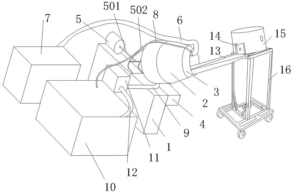
[0025] In this embodiment, the structure of the present invention is described in detail with reference to the accompanying drawings.
[0026] Please refer to the accompanying drawings, the steel ball drying and cleaning equipment provided by the present invention includes:
[0027] The drum mechanism includes an outer cylinder 2 slanted and pivotally connected to the machine base 1 . A rotatable cleaning inner cylinder 3 is coaxially arranged in the outer cylinder 2 , and the inner cylinder 3 is driven by the cleaning motor 4 through the transmission mechanism.
[0028] The overturning mechanism connects the outer cylinder 2 and the base 1, and the outer cylinder 2 and the inner cylinder 3 are simultaneously tilted and turned over by the cylinder 5 of the overturning mechanism.
[0029] The drying mechanism includes a hot air pipe 6 inserted into the inner cylinder 3 , and the hot air pipe 6 is connected to the hot air blower 7 .
[0030] The water circulation system include...
PUM
Abstract
The invention relates to a steel ball drying and cleaning device which comprises an outer cylinder and an inner cylinder, a turnover mechanism, a drying mechanism, a water circulation system and a controller. The outer cylinder and the inner cylinder are obliquely arranged, the inner cylinder is driven by a motor, the turnover mechanism is connected with the outer cylinder and a base, the outer cylinder and the inner cylinder simultaneously and obliquely turn over through an air cylinder of the turnover mechanism, the drying mechanism comprises a hot air pipe inserted into the inner cylinder, the hot air pipe is connected with an air heater, the water circulation system comprises a drainage pipe, at least one shower pipe and a cleaning fluid tank, one end of each shower pipe is communicated with the cleaning fluid tank through a pump, the other end of the shower pipe is fixed on the outer wall of the outer cylinder and inserted into the inner cylinder, the drainage pipe is connected at the bottom of the outer cylinder and communicated with at least one water return pipe through a fluid reverser, and the controller is connected with the cleaning motor, the air heater, the pumps, the air cylinder and the fluid reverser and controls the cleaning motor, the air heater, the pumps, the air cylinder and the fluid reverser. The steel ball drying and cleaning device is safe, reliable, simple to operate, convenient to feed and discharge and high in production efficiency, the mixing occurring rate of steel balls can be greatly decreased, less water for cleaning is used, and the production cost of enterprises is reduced.
Description
technical field [0001] The invention relates to the technical field of steel ball cleaning and drying equipment, in particular to a steel ball drying equipment [0002] Clean equipment. Background technique [0003] The steel ball in the bearing is an essential part. During the manufacturing process of the steel ball, the steel ball needs to be cleaned and dried to ensure the effect of the subsequent heat treatment of the steel ball. First of all, in the prior art steel ball drying and cleaning equipment, the drying and cleaning are set separately, and the continuous production line or manual drying and cleaning are mostly used. The continuous production line is suitable for large-scale drying of steel balls with the same diameter. Cleaning, but when small batches and steel ball diameters are constantly changing, this kind of equipment is very easy to cause mixed use of steel balls, while manual cleaning and drying in separate steps, the production efficiency is low, the la...
Claims
Application Information
Patent Timeline
Application Date:The date an application was filed.
Publication Date:The date a patent or application was officially published.
First Publication Date:The earliest publication date of a patent with the same application number.
Issue Date:Publication date of the patent grant document.
PCT Entry Date:The Entry date of PCT National Phase.
Estimated Expiry Date:The statutory expiry date of a patent right according to the Patent Law, and it is the longest term of protection that the patent right can achieve without the termination of the patent right due to other reasons(Term extension factor has been taken into account ).
Invalid Date:Actual expiry date is based on effective date or publication date of legal transaction data of invalid patent.