
Integrated injection molding device of injection molding machine

A technology for injection molding machines and cylinder liners, applied in the field of integrated injection molding devices, can solve problems such as poor injection molding precision, low injection molding accuracy, and injection molding failure, and achieve the effects of reduced overall cost investment, improved control accuracy, and simplified overall structure

Inactive Publication Date: 2015-04-15
SUZHOU LIZHU MACHINERY
View PDF3 Cites 3 Cited by
  • Summary
  • Abstract
  • Description
  • Claims
  • Application Information

AI Technical Summary

Problems solved by technology

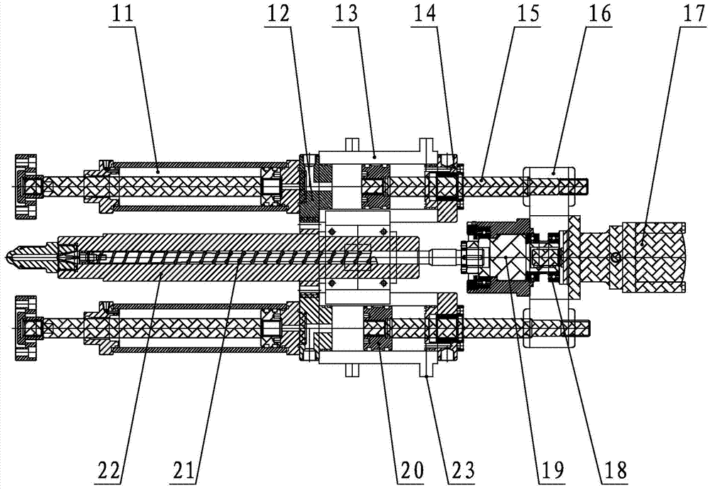
[0004] The injection molding device is installed on the sliding seat of the injection molding machine, and the overall movement of the entire injection molding device is driven by the seat oil cylinder 11 to realize the docking and separation of the injection nozzle and the mold, but it needs to move synchronously through two symmetrical seat oil cylinders 11 In order to accurately realize the overall movement of the injection molding device, if there is an asynchronous state, the injection nozzle cannot be accurately docked with the mold, resulting in injection failure, and the structure of the double cylinder setting is complicated and the cost is high;
[0005] The shooting cylinder 13 is provided with a shooting cylinder rear cover 12 and a shooting cylinder front cover 14 to form a closed cylinder body. The existing structure is also set as two symmetrical shooting cylinders 13. The material storage and injection actions are realized through the coordinated and synchronous actions of the injection cylinder mandrel 15 and the piston 20 of the two injection cylinders 13. This structure also has related parts that are easily damaged due to asynchrony, and the structure is also complicated and costly. high;
[0006] Between the two shooting cylinders 13 are the screw barrel 22, the screw 21 and the hydraulic motor 17 arranged in the screw barrel 22, the transmission shaft 19 of the hydraulic motor 17 is connected with the screw 21 to drive the rotation of the screw 21 and Realize material storage, and at the same time, install the injection cylinder 13 on both sides and the hydraulic motor 17 into one body through the connecting plate 16, and set the bearing 18 at the connection between the hydraulic motor 17 and the connecting plate 16. When storing and injecting materials, the hydraulic motor 17 needs to move synchronously with the mandrel 13 of the injection cylinder. Therefore, this connection method also has the problem that the injection cylinder 13 on both sides is not synchronized with the middle hydraulic motor 17 and the screw 21. It will also be caused by poor mobility and coordination. The damage of related parts may lead to poor injection accuracy, complex structure and high cost investment
[0007] In addition, since the storage of the screw 21 is controlled by the hydraulic motor 17, there is no precise unit of measurement in the actual working process, and it is only controlled by the number of turns of the hydraulic motor 17, so there is often a deviation in the storage volume , resulting in a deviation in the amount of injection in the subsequent injection process, resulting in low injection molding accuracy of the product
[0008] To sum up, the double-cylinder injection molding device for direct-pressure horizontal injection molding machines with the existing structure shown in Figure 1 has complex structure, high cost investment, poor mobility and coordination, and is easy to damage other parts, storage materials and injection materials. Therefore, how to avoid the above problems is a problem that needs to be considered in the design of the injection molding device of the direct pressure horizontal injection molding machine.

Method used


Image

  • Integrated injection molding device of injection molding machine
  • Integrated injection molding device of injection molding machine
  • Integrated injection molding device of injection molding machine

Examples


Embodiment Construction

[0037] The following will clearly and completely describe the technical solutions in the embodiments of the present invention with reference to the drawings in the embodiments of the present invention.

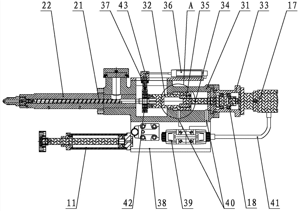
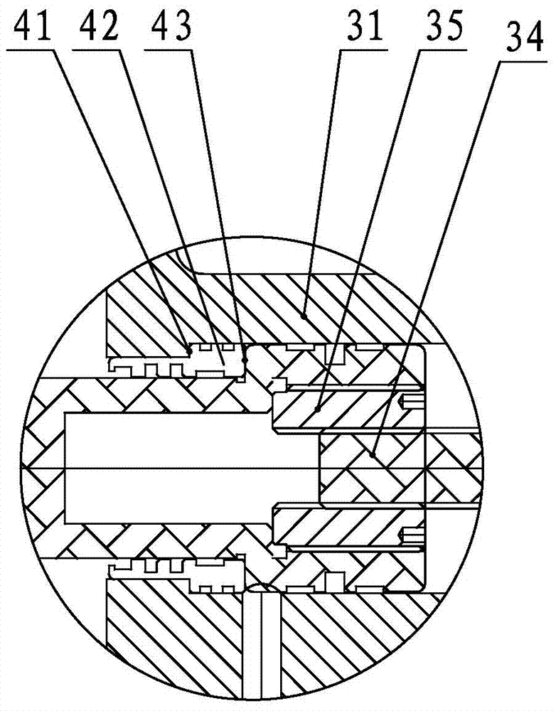
[0038] refer to figure 2 and 3 , the present invention provides an integrated injection molding device for an injection molding machine. The injection molding device is installed on the sliding seat of the injection molding machine through the injection cylinder support seat 38 at the bottom, which includes a cylinder sleeve 31, and the injection end of the cylinder sleeve 31 is installed with The screw barrel 22, the screw barrel 22 is provided with a screw 21; the middle of the shooting cylinder sleeve 31 is provided with an integrated shooting cylinder mandrel 32; A hydraulic motor 17 is installed, and the hydraulic motor 17 is provided with a spline transmission shaft 34 with a spline structure at the end, and the spline transmission shaft 34 is connected with the motor f...


PUM


Abstract

The invention discloses an integrated injection molding device of an injection molding machine. The integrated injection molding device comprises an injection cylinder sleeve, wherein a screw material barrel is arranged at the injection end of the injection cylinder sleeve; a screw is arranged in the screw material barrel; an integrated injection cylinder mandrel is arranged in the middle of the injection cylinder sleeve; a motor fixing seat is arranged at the driving end of the injection cylinder sleeve; an oil pressure motor is arranged on the motor fixing seat and is provided with a spline transmission shaft of which the end part is of a spline structure; the spline transmission shaft is connected with the motor fixing seat through a bearing; one end of the integrated injection cylinder mandrel is connected with the screw, and the other end of the integrated injection cylinder mandrel is connected with the spline transmission shaft through a spline; an injection cylinder supporting seat is connected with a seat boss oil cylinder. Due to the arrangement of the spline and the spline transmission shaft, material storage and material injection are integrated; the material storage and the material injection can be realized without an extra injection molding driving injection cylinder; furthermore, the movement of the whole integrated injection molding device can be realized only through one seat boss oil cylinder; therefore, minimization, compactness and low-cost investment of the injection molding device are realized, and the integrated injection molding device runs steadily and reliably.

Description

technical field [0001] The invention relates to a direct pressure horizontal injection molding machine, in particular to an integrated injection molding device of the injection molding machine. Background technique [0002] Injection molding machine, also known as injection molding machine or injection machine, is the main molding equipment for making thermoplastic or thermosetting materials into various shapes of plastic products with plastic molding molds. Among them, the direct pressure horizontal injection molding machine has a large clamping stroke, The advantages of high clamping precision, small template deformation, and low requirements on the height of the factory building are suitable for injection molding of specific products and occasions. [0003] Shown in Fig. 1 is the top view diagram of the injection molding device of a kind of direct pressure horizontal injection molding machine of prior art: [0004] The injection molding device is installed on the sliding...

Claims


Application Information

Patent Timeline
IPC IPC(8): B29C45/47B29C45/76B29C45/82
CPCB29C45/1775B29C45/47B29C45/76B29C45/82B29C2045/1792B29C2945/76658B29C2945/76665
Inventor 骆小锋
Owner SUZHOU LIZHU MACHINERY
Learn More