Control method of vehicle power generating set

A technology of a power generation device and a control method, which can be applied to control devices, vehicle components, auxiliary drive devices, etc., can solve the problems of vehicle loss of control, strong impact, and difficult to bite, and achieve the purpose of improving service life, ensuring safety, and increasing commerciality. Effect

Inactive Publication Date: 2015-04-15
KYMCO
View PDF7 Cites 1 Cited by
  • Summary
  • Abstract
  • Description
  • Claims
  • Application Information

AI Technical Summary

Problems solved by technology

[0003] Although the aforementioned patented technology can thus achieve the effect of switching to drive the vehicle to move or to drive the generator to generate electricity, because the crankshaft of the internal combustion engine is connected to the generator for attached operation, the crankshaft of the internal combustion engine is not at that time Therefore, when the internal combustion engine is attached to the generator, especially when it is running at high speed, the clutch gears engaging the two shafts will not easily engage, and during the difficult engagement period, the two gears will have strong friction due to the high speed of the engine. Impact and great noise make it less commercially viable and easily damage gears
What's more, when the speed difference between the crankshaft of the internal combustion engine and the drive shaft of the generator is too large, the shaft connection will easily cause irregular momentum, which may cause the vehicle to lose control

Method used


Image

  • Control method of vehicle power generating set
  • Control method of vehicle power generating set
  • Control method of vehicle power generating set

Examples


Embodiment Construction

[0032] Embodiments of the present invention will be described below with reference to the drawings.

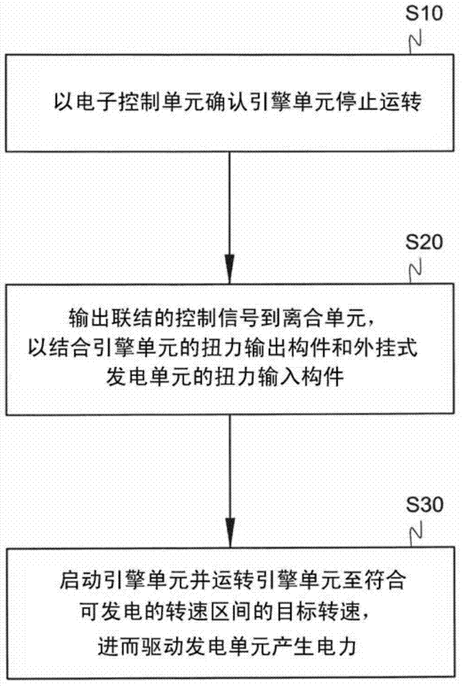
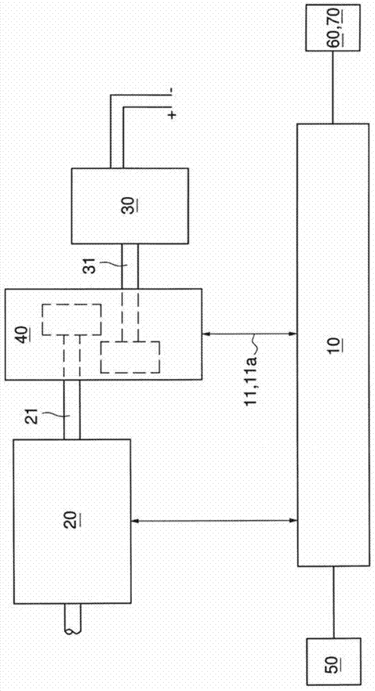
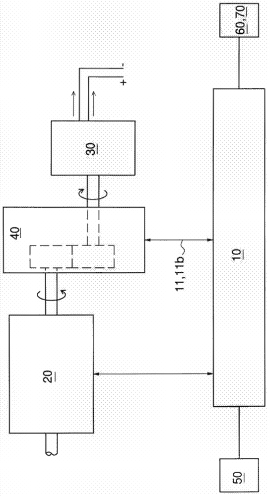
[0033] First please refer to figure 1 The step flow chart of the embodiment of the control method of the vehicle power generating device of the present invention shown, figure 2 The system schematic diagram of the embodiment of the control mechanism of the vehicle power generation device of the present invention in the non-power generation state and image 3 shown figure 2 The system schematic diagram of the power generation state of the embodiment of the present invention. The vehicle power generation device in the control method of the vehicle power generation device in this embodiment includes an electronic control unit 10, an engine unit 20, and an external power generation unit selectively driven by the engine unit 20 (using a clutch unit 40 described later). unit 30 , and a clutch unit 40 located between the engine unit 20 and the external generator unit 30 . The e...


PUM


Abstract

The invention provides a control method of a vehicle power generating set. The vehicle power generating set comprises an engine unit, an external mounting generator unit, a clutch unit and an electronic control unit. The engine unit outputs power through a torque output component; the external mounting generator unit receives power through a torque input component to operate and generate power; the clutch unit is used for electrically combining or separating the torque output component with/from the torque input component. The control method thereof comprises the following steps that the engine unit is confirmed to shut down through the electronic control unit; a linking control signal is output to the clutch unit to combine the torque output component of the clutch unit with the torque input component of the external generator unit; and the engine unit is started and operated to achieve a target speed, and further the external mounting generator unit is driven to generate power.

Description

technical field [0001] The present invention relates to a control method of a vehicle power generation device, in particular to a control method of a vehicle power generation device that uses a clutch unit combined with a torque output member and a torque input member of an external power generation unit after the engine unit stops running. Background technique [0002] Traditional portable engine generators can only be used for power generation and power supply, and cannot be used to drive vehicles; and the invention patent of US Publication No. US6820576 "Vehicles Driven by Internal Combustion Engines with Generators" discloses a vehicle that utilizes The technology of an internal combustion engine driving a non-vehicle generator. A vehicle driven by an internal combustion engine includes a power conversion element provided between a crankshaft of the internal combustion engine and drive wheels and having a centrifugal clutch connecting the crankshaft and the drive wheels,...

Claims


Application Information

Patent Timeline
Patent Type & Authority Applications(China)
IPC IPC(8): B60K25/00B60K17/02
Inventor 郭岳霖陈俊雄
Owner KYMCO
Why Eureka
Try Eureka