

Variable valve device of internal combustion engine
An internal combustion engine and valve technology, which is applied to valve devices, mechanical equipment, engine components, etc., can solve the problems of complicated working methods of switching pins, and achieve the effect of simplifying the structure and working methods.
Inactive Publication Date: 2015-04-15
SUZUKI MOTOR CORP
View PDF4 Cites 8 Cited by
- Summary
- Abstract
- Description
- Claims
- Application Information
AI Technical Summary
Problems solved by technology
Moreover, there is a problem that after the movement of the cam holder is completed, the switching pin needs to be quickly drawn out from the guide groove, so the working method of the switching pin is complicated.
Method used
View moreImage
Smart ImageViewing Examples

Examples
other Embodiment approach
[0105] The embodiments have been described above, but the present invention is not limited thereto. For example, in the above-described embodiment, the 2-stage variable valve device applied to the high-speed cam 41 and the low-speed cam 42, but as Figure 9 As shown in the cam holder 4A, if the second cam 42 is set as a stop cam having a peripheral surface (all of which are base circle portions 42 ) whose lift is 0, the valve stop function can be realized. According to such a configuration, the structure and operation method of the mechanism for switching the cam can be simplified, and the valve can be stopped.
Login to View More PUM
 Abstract
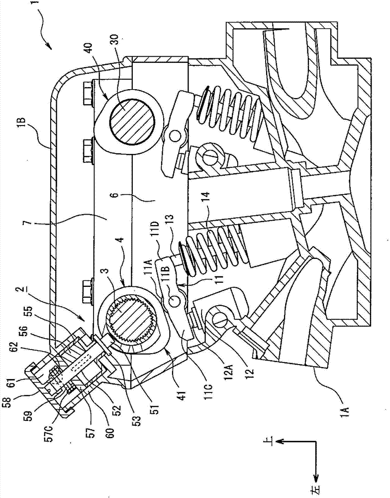
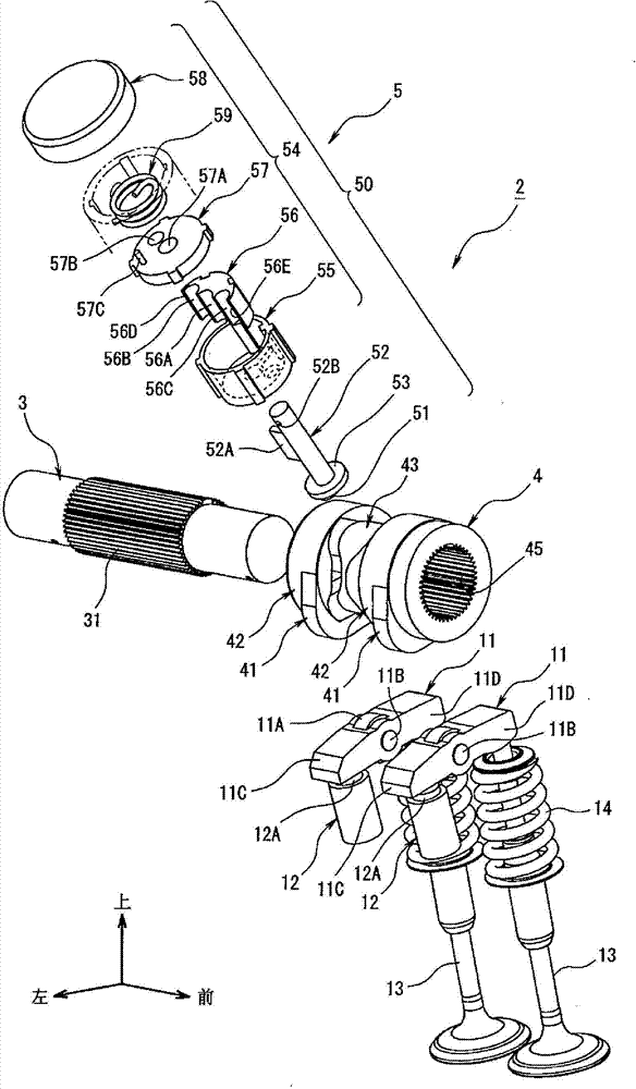
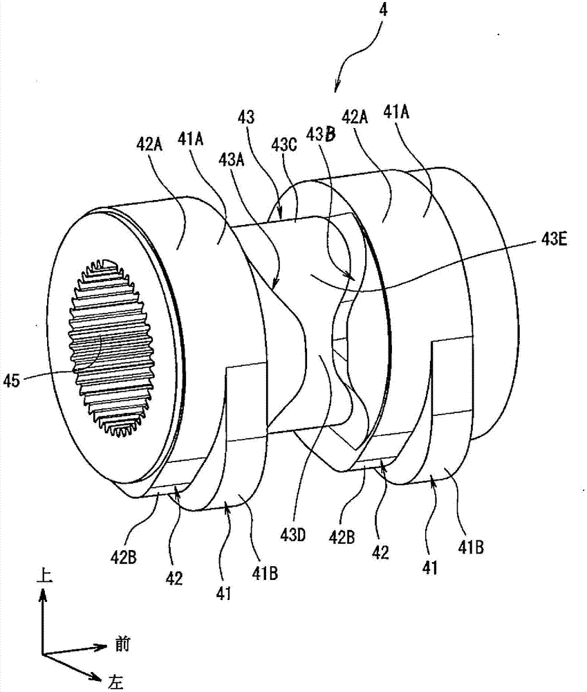
Provided is a variable valve device of an internal combustion engine, and structure and working method of the device are simplified. The device is provided with a cam support (4) and a cam switchover portion (5). The cam support (4) makes the valve operate to move to a first position through a high-speed cam (41) and makes the valve operate to move to a second position through a low-speed cam (42). The outer peripheral surface of the device is provided with a guide groove (43). The guide groove (43) is provided with a pair of opposite side walls. One of the pair of side walls is a first switchover cam (43A) which makes the cam support (4) move to the first position, and the other is a second switchover cam (43B) which makes the cam support (4) move to the second position. The cam switchover portion is provided with a switchover pin (51) which is inserted into the guide groove (43), and a driving portion (50) which makes the switchover pin (51) move to a first pin position or a second pin position on an axial direction of a cam shaft (3), in the first pin position, the switchover pin can contact with the first switchover cam (43A), and in the second pin position, the switchover pin can contact with the second switchover cam (43B).
Description
technical field [0001] The present invention relates to a variable valve device for an internal combustion engine that moves a cam carrier provided with a plurality of cams in the axial direction of a camshaft to change operating characteristics of a valve. Background technique [0002] Conventionally, as a variable valve device for an internal combustion engine, a variable valve device (for example, Refer to Patent Document 1). In this variable valve device, the switching pin provided on the operating member capable of reciprocating in the radial direction of the cam holder is drawn and inserted into the helical guide groove formed on the outer periphery of the cam holder, thereby allowing the cam holder to move in the axial direction. move. [0003] prior art literature [0004] patent documents [0005] Patent Document 1: Patent No. 430618 Contents of the invention [0006] The problem to be solved by the invention [0007] However, in the above-mentioned con...
Claims
Login to View More Application Information
Patent Timeline
 Patent Type & AuthorityApplications(China)
IPC IPC(8): F01L13/00
CPCF01L13/0036F01L2001/0473F01L2013/0052F01L1/185F01L1/267F01L2001/0537F01L2013/101F01L2305/00
Inventor大泽宏
OwnerSUZUKI MOTOR CORP