Super energy-saving and safe intelligent electric heater

An electric heater and super energy-saving technology, applied in electric heating systems, space heating and ventilation details, heating methods, etc., can solve the problems of reducing the service life of the controller, arc oxidation at the circuit connection, and high power consumption, reaching The effect of improving heat dissipation efficiency, avoiding safety accidents and prolonging service life

Inactive Publication Date: 2018-07-31
湖南川路科技有限责任公司
View PDF6 Cites 0 Cited by
  • Summary
  • Abstract
  • Description
  • Claims
  • Application Information

AI Technical Summary

Problems solved by technology

[0003] The disadvantages of existing electric heaters, especially the controllers (electric heating fireboxes) used for movable box-type electric heaters, are large power consumption, large waste of electric energy, large gaps in temperature control, and violent temperature changes. Large, affecting the comfort of heating, the safety and durability of the control circuit is not enough, it is easy to burn out and cause major safety accidents such as fire
[0004] On the one hand, in the existing temperature control device for movable box-type electric heaters, only one integral circuit board is set in the control panel where switches and indicating and displaying elements are installed, including silicon controlled rectifiers and other electronic devices that produce large heat. Components and other electronic components are all concentratedly installed on such a small circuit board. Since the existing temperature control device is attached to the side box board of the electric heating fire box, the components in the temperature control device are between the side box board and the side box board. Between the heating elements, there is no heat insulation layer between the components in the temperature control device and the high temperature area around the heating element. The installation place of the components in the temperature control device is often in the high temperature area. Electronic components such as electronic components have a large load-carrying power and produce a lot of heat. It is difficult to achieve the specified heat dissipation purpose through the existing heat sink. Other components on the circuit board are easy to age or burn out, which often causes the temperature control device to burn out easily and is not durable, which can easily lead to major safety accidents such as fire
[0005] On the other hand, the existing electric heater adopts thermistor timing control or potentiometer stepless temperature adjustment control. According to the rated power of the heater, the heater is turned on and off with the full rated power to make the heater realize the so-called constant temperature, and Very high frequency of on and off
This kind of full-load rated power is frequently turned on and off, the temperature increases and decreases violently, and the inertia of heating or cooling is very large, which often deviates from the heating comfort temperature value by a large amount, which not only reduces the heating comfort (often produces a burning sensation) or cold feeling), and waste a lot of electric energy; secondly, frequent power-on at full-load rated power, sudden heating or sudden stop of heating when power is off, large starting current, which also increases heating power consumption; thirdly, frequent power-on at full-load rated power , power failure, the impact on the controller is large, and it is easy to cause arc oxidation or burnout at the circuit connection, which greatly reduces the service life of the controller, and often leads to major safety accidents such as fire, and has a negative impact on the associated power grid, electrical appliances also has a great influence

Method used


Image

  • Super energy-saving and safe intelligent electric heater
  • Super energy-saving and safe intelligent electric heater

Examples


Embodiment Construction

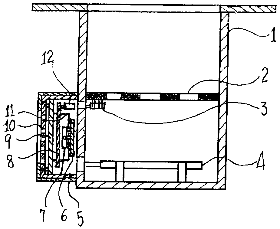
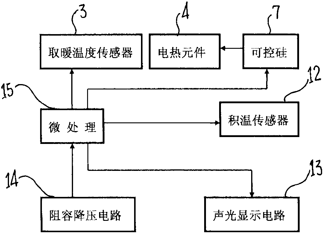
[0035] Such as figure 1 , 2As shown, the ultra-energy-saving and safe intelligent electric heater of the present invention includes a foot rest mechanism 2, an electric heating element 4, and a temperature control device 5 installed in a box body 1. A heating temperature sensor 3 is installed on the foot rest mechanism 2, and a heating temperature sensor 3 is installed on the temperature control device. 5, the accumulated temperature sensor 12 is installed, and the heating temperature sensor 3 and the accumulated temperature sensor 12 are respectively connected with the temperature control device 5.

[0036] The temperature control device 5 has a thyristor 7, and the thyristor 7 is installed on a special thyristor mounting board 6 (a circuit board for installing the thyristor or the thyristor and its related components), and the thyristor mounting board 6 and the circuit board 8 (the circuit board on which electronic components such as microprocessors are installed) are arran...


PUM


Abstract

The invention discloses an ultra-energy-saving and safe intelligent electric heater. In order to overcome the disadvantages of existing electric heater controllers, such as high heating power consumption, poor heating comfort, short service life, and easy fire hazards, the present invention installs a heating temperature sensor on the foot rest mechanism, and installs a heating temperature sensor on the temperature control device. The accumulated temperature sensor is installed, the thyristor of the temperature control device is installed on the thyristor mounting plate, and the thyristor mounting plate and the circuit board are arranged on different planes at intervals, and the sub-radiating fins connected to the thyristor are clamped with the mother heat sink The silicon controlled rectifiers are respectively connected to the electric heating element and the microprocessor, and the microprocessor is respectively connected to the resistance-capacity step-down circuit, the heating temperature sensor, and the accumulated temperature sensor. The invention is used for electric heating, and the test results show that it saves more than 37% of electricity, prolongs the service life by more than 5 times, makes heating more comfortable, can avoid safety accidents such as fire, has a high degree of intelligence, and has little impact on associated power grids and electrical appliances.

Description

technical field [0001] The invention relates to an electric heating appliance, in particular to an ultra-energy-saving and safe intelligent electric heater. Background technique [0002] Electric heaters, especially movable box-type (usually open wooden box) electric heaters (electric heating fire boxes) with a footrest mechanism, because of their convenience in heating, especially in the way of warming feet , in line with the principle of cold from the feet in traditional Chinese medicine and the reality of dehumidification in the south, it is more and more popular among people. This heating method can improve the blood circulation of the feet and legs, and can prevent rheumatism and foot pain. [0003] The disadvantages of existing electric heaters, especially the controllers (electric heating fireboxes) used for movable box-type electric heaters, are large power consumption, large waste of electric energy, large gaps in temperature control, and violent temperature changes...

Claims


Application Information

Patent Timeline
Patent Type & Authority Patents(China)
IPC IPC(8): F24D13/00F24D19/10
Inventor 黄子晋黄子恒黄泰瑜
Owner 湖南川路科技有限责任公司
Why Eureka
Try Eureka