An electric field monitoring device and method for electrokinetic remediation of polluted soil

A technology for electric remediation and contaminated soil, applied in electrostatic field measurement and other directions, can solve problems such as the difference between electric field strength and theoretical value, soil medium inhomogeneity, etc., to achieve the effect of optimizing electric field conditions and improving the efficiency of electric remediation

Active Publication Date: 2017-06-30
SHENYANG INST OF APPL ECOLOGY CHINESE ACAD OF SCI
View PDF5 Cites 0 Cited by
  • Summary
  • Abstract
  • Description
  • Claims
  • Application Information

AI Technical Summary

Problems solved by technology

[0004] As a complex medium different from water, the spatial distribution of the electric field intensity of soil under the condition of an external electric field can only be obtained by theoretical calculation (Li et al., 2010), and the inhomogeneity of the soil medium causes the actual electric field intensity Spatial difference from theoretical value

Method used


Image

  • An electric field monitoring device and method for electrokinetic remediation of polluted soil
  • An electric field monitoring device and method for electrokinetic remediation of polluted soil
  • An electric field monitoring device and method for electrokinetic remediation of polluted soil

Examples


Embodiment 1

[0040]The contaminated soil repaired in this embodiment is the oil-contaminated soil configured in the laboratory. The soil collected is brown soil, which is passed through a 2mm sieve after natural air-drying in the room. The oil is collected from an oil pit in Shuguang Oil Production Plant of Liaohe Oilfield, and the oil content is 50g. / kg oil-contaminated soil. After oil and soil are mixed evenly, divide into 4 treatments, adjust the moisture content with deionized water to 5%, 10%, 15% and 25% respectively, and pack into the soil box respectively (long 30cm * wide 30cm * high 10cm ).

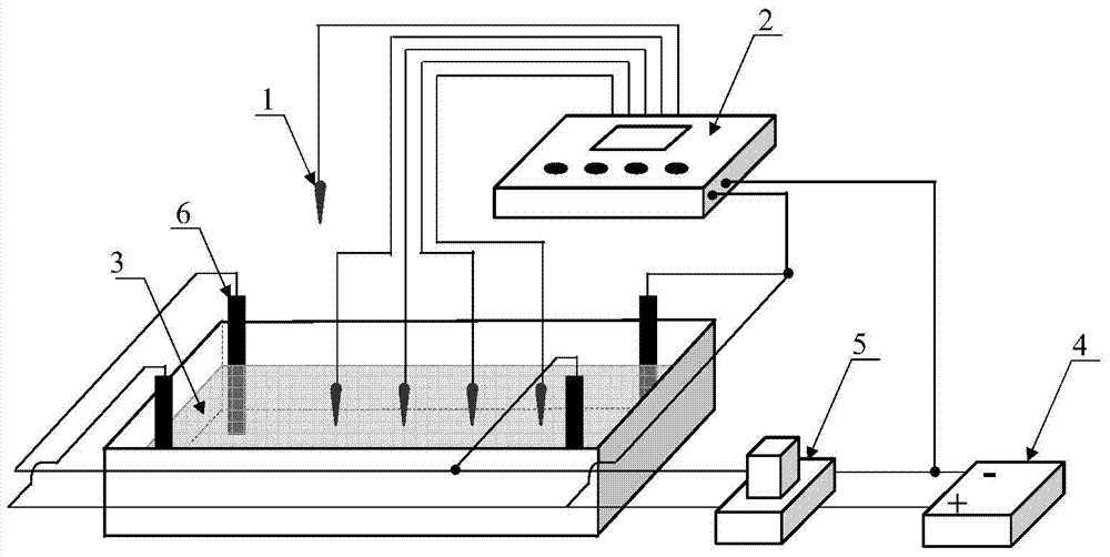
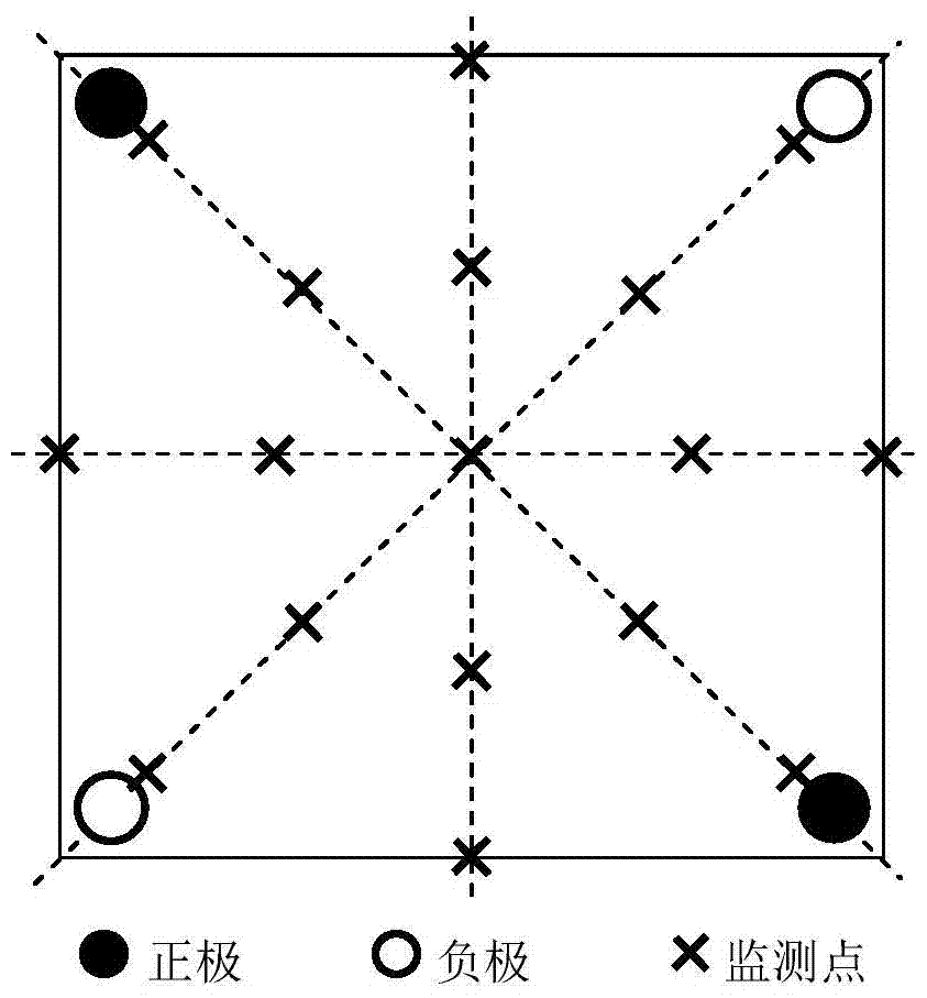
[0041] in contaminated soil according to image 3 Four electrodes 6 are arranged as shown. The electrode 6 is made of graphite electrode, with a diameter of 1cm and a height of 11cm. The applied voltage is 30V, and the polarity of the two adjacent electrodes is kept opposite. Timing switching at intervals of 4 hours. in contaminated soil according to image 3 Probe 1 is arranged, and th...

Embodiment 2

[0053] The polluted soil to be repaired is heavy metal cadmium polluted soil, the soil is sandy soil, and the cadmium content is 10ppm. Divide into 4 treatments, adjust moisture content to 10%, 15%, 20% and 25% with deionized water respectively, and pack into soil boxes (length 20cm×width 10cm×height 10cm) respectively.

[0054] in contaminated soil according to Figure 5 Four electrodes 6 are arranged as shown. The electrode 6 is made of graphite electrode with a diameter of 1 cm and a height of 11 cm. The applied voltage is 20V, and the polarity of the electrodes is not switched. in contaminated soil according to Figure 5 Probe 1 is arranged as shown, the material of probe 1 is iron-nickel alloy, the length of the probe is 10 cm, and the diameter is 1 cm.

[0055] The specific operation process includes:

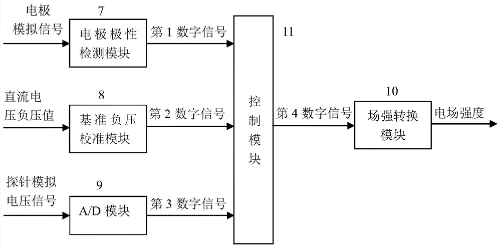
[0056] The probe 1 is evenly inserted into the electric restoration soil 3, and is connected with the A / D module 9 inside the main control unit 2 through wires; the el...


PUM


Abstract

The invention relates to an electric field monitoring device and method for electrodynamic restoration of polluted soil. The device includes a probe and a main control unit; the main control unit includes an electrode polarity detection module, a reference negative pressure calibration module, an A / D module, and a field strength Conversion module, control module. The probe is inserted into the electrically repaired soil, and the collected voltage signal is output to the main control unit. The main control unit performs benchmark correction, analog-to-digital conversion on the voltage signal, and calculates the electric field strength value according to the preset parameters. The method includes processing the voltage signal of the polluted soil collected by the probe, and calculating the electric field strength value according to the set parameters, so as to monitor the electric field strength in the electrokinetic restoration process of the polluted soil in real time. The invention can realize the real-time monitoring of the electric field intensity in the electrokinetic restoration process of polluted soil, and effectively improve the electrokinetic restoration efficiency.

Description

technical field [0001] The invention relates to the technical field of soil electric field monitoring in electrokinetic restoration, in particular to an electric field monitoring device and method for electrokinetic restoration of polluted soil. Background technique [0002] The electric remediation method of polluted soil is a new emerging technology at present. The electrokinetic remediation of polluted soil is to insert electrodes into the polluted soil to form an electrode matrix, apply a weak direct current to form an electric field, and under the action of electrokinetic effect, the pollutants in the soil can be effectively removed. [0003] Previous research results have shown that during the electrokinetic remediation process, the degradation efficiency of organic pollutants in soil is positively correlated with the potential drop (Li et al., 2014), and the migration rate of heavy metal pollutants is also closely related to the electric field strength. Therefore, el...

Claims


Application Information

Patent Timeline
Patent Type & Authority Patents(China)
IPC IPC(8): G01R29/12
Inventor 郭书海吴波邹志红李凤梅李刚
Owner SHENYANG INST OF APPL ECOLOGY CHINESE ACAD OF SCI
Why Eureka
Try Eureka