Calibration device and calibration method for radio frequency homing-based semi-physical simulation system
A semi-physical simulation and radio frequency simulation technology, applied in the direction of electrical testing/monitoring, can solve the problem of inability to align the position of the column and the center calibration of the array, the deviation of the data from the real technical state of the system, and the inability to fully and truly reflect the radio frequency semi-physical simulation system technology Status and other problems, to achieve the effect of high calibration progress, convenient installation and convenient operation
- Summary
- Abstract
- Description
- Claims
- Application Information
AI Technical Summary
Problems solved by technology
Method used
Image

Examples
Embodiment 1
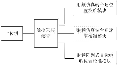
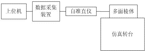
[0041] Embodiment 1: the method for calibrating the angular position of the radio frequency simulation turntable, comprising a 23-sided prism and a photoelectric autocollimator with a resolution of 0.1 second, a radio frequency simulation turntable angular position calibration module composed of, the polyhedral prism is fixedly connected to the radio frequency On the table of the simulation turntable, the read head of the optical autocollimator coaxial with the radio frequency simulation turntable is aligned with the center of the polyhedral prism reflector, fixed on the fixed support seat, and connected to the data acquisition device connected to the host computer connected, the steps include the following:
[0042] (1) Align the autocollimator with the first face of the polyhedral prism, and record the readings of the autocollimator;
[0043] (2) According to the angle of the polyhedral prism, rotate the RF simulation turntable clockwise by the corresponding angle, and recor...
Embodiment 2
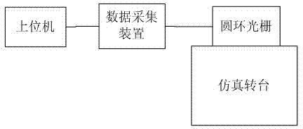
[0048] Embodiment 2: The method for calibrating the angular rate of the radio frequency simulation turntable includes a ring grating, the ring grating includes a grating ring and a grating head, is installed on a grating mount, and is connected to the table of the radio frequency simulation turntable, the grating Align the grating ring with the head and connect it to the data acquisition device connected to the host computer. The host computer and the data acquisition device are connected through a wireless transmitting and receiving module. The steps include the following: When the radio frequency simulation turntable moves, the time base The circuit starts timing immediately, and at the same time, the angle measurement device records the rotation angle of the angular rate calibration device, records and analyzes the data through the data acquisition and processing system, and obtains the angular rate parameter index, which is compared with the angular rate parameter index inpu...
Embodiment 3
[0053] Embodiment 3: the method for calibrating the position of the radio frequency array target speaker includes the Leica TCR1201 total station for 0.1 seconds, the lens of the total station is aimed at the target speaker, and is connected to the data acquisition device connected with the host computer connected, the steps include the following steps: by measuring the angle and distance of the array target speakers, recording the corresponding data, and analyzing and processing the data received by the host computer to obtain the center of the array and the positions and distances between the speakers. The angular relationship is used to realize the calibration of the radio frequency array target.
[0054] The calibration device is calibrated by the metrology technical institution. The angle measurement error of the calibration device is 2 seconds, and the rate stability is up to 1×10 -6 . The on-site test was carried out in the radio frequency simulation laboratory. Throug...
PUM
| Property | Measurement | Unit |
|---|---|---|
| Diameter | aaaaa | aaaaa |
Abstract
Description
Claims
Application Information