Source driver of display device

一种源极驱动器、放大器的技术,应用在静态指示器、仪器等方向,能够解决源极驱动器偏移电压差异、减小源极驱动器良率等问题

Active Publication Date: 2015-04-15
SILICON WORKS CO LTD
View PDF5 Cites 26 Cited by
  • Summary
  • Abstract
  • Description
  • Claims
  • Application Information

AI Technical Summary

Problems solved by technology

Therefore, a difference in offset voltage between source drivers may occur, reducing the yield of source drivers

Method used


Image

  • Source driver of display device
  • Source driver of display device
  • Source driver of display device

Examples


Embodiment Construction

[0022] Preferred embodiments of the invention, examples of which are shown in the accompanying drawings, will be described in more detail below. Wherever possible, the same reference numbers will be used throughout the specification and drawings to refer to the same or like parts.

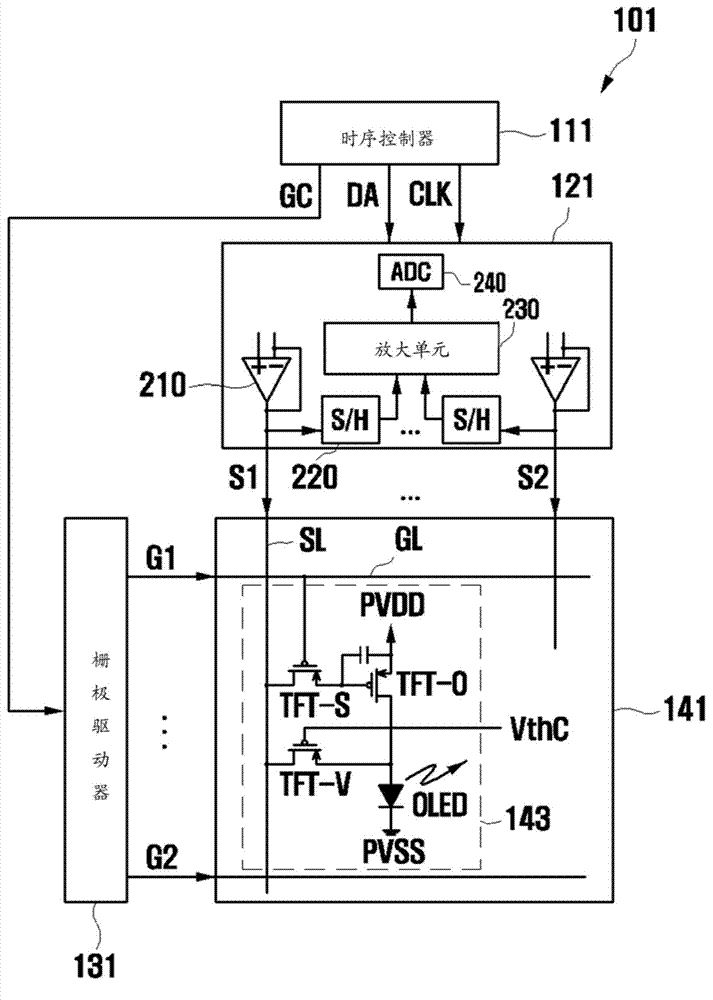
[0023] figure 1 It is a block diagram of the display device 101 to which the embodiment of the present invention is applied. refer to figure 1 , the display device 101 may include a timing controller 111 , a source driver 121 , a gate driver 131 and a display panel 141 .

[0024] The timing controller 111 can transmit the image data DA and the clock signal CLK to the source driver 121 , and transmit the gate control signal GC to the gate driver 131 .

[0025] The source driver 121 may receive the clock signal CLK and the image data DA from the timing controller 111, process the image data DA synchronously with the clock signal CLK, and output the source driving signals S1 and S2 to the display p...


PUM


Abstract

A source driver may include: a transmission line configured to transmit an output signal of a sample and hold circuit which stores pixel information of an organic light emitting diode (OLED) cell; an amplifier is formed a first offset voltage at an input terminal by a parasitic capacitor of the transmission line; and an offset voltage storage unit configured to store the first offset voltage outputted from the amplifier as a second offset voltage while the transmission of the output signal of the sample and hold circuit through the transmission line is turned off, and offset the first offset voltage by providing the second offset voltage to the input terminal of the amplifier when the output signal of the sample and hold circuit is transmitted through the transmission line.

Description

technical field [0001] The present invention relates to a display device, and more particularly, to a source driver for driving a display panel. Background technique [0002] With the development of information technology (IT), the use of display devices has rapidly increased. A display device includes a display panel for displaying images and a plurality of drivers for driving the display panel. A part of drivers may include a gate driver for driving scan lines formed in the display panel, and another part of drivers may include a source driver for driving data lines formed in the display panel. [0003] In the case where the display panel uses an organic light emitting diode (OLED), the source driver includes a plurality of sample and hold (S / H) circuits configured to detect Changes in pixel information. [0004] A sample and hold circuit is provided at each output channel of the source driver to detect pixel information. Therefore, the source driver includes a plurali...

Claims


Application Information

Patent Timeline
Patent Type & Authority Applications(China)
IPC IPC(8): G09G3/32
CPCG09G3/3208G09G3/3291G09G2300/043G09G2300/0819G09G2310/027G09G2310/0294G09G2320/0233G09G2320/045G09G3/32G09G2310/0291
Inventor 闵庚直全炫奎郑镛益赵贤镐金永福
Owner SILICON WORKS CO LTD
Why Eureka
Try Eureka