Audio code products and audio code communication channel circuits
A voice-code communication channel and circuit technology, applied in the electronic field, can solve the problem of uncontrollable signal amplitude, and achieve the effect of improving the range of the host
- Summary
- Abstract
- Description
- Claims
- Application Information
AI Technical Summary
Problems solved by technology
Method used
Image
Examples
Embodiment 1
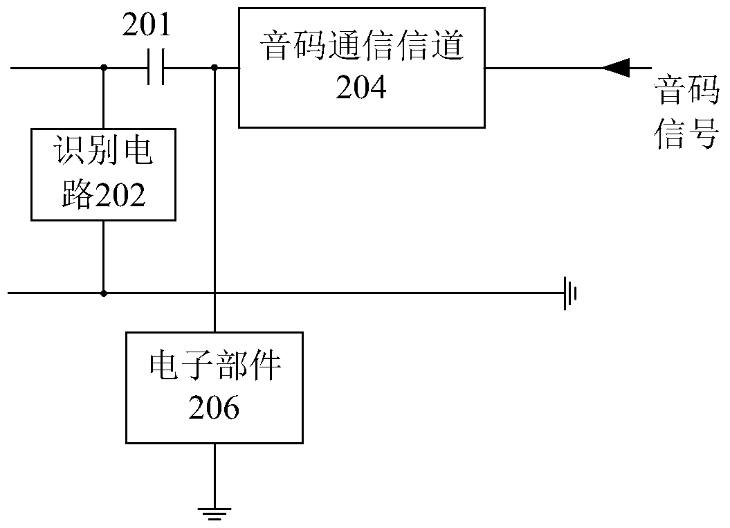
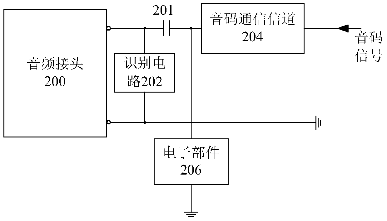
[0032] This embodiment provides a sound code communication channel circuit, figure 2 A schematic structural diagram of the voice code communication channel circuit provided in this embodiment.
[0033] like figure 2 As shown, the audio code communication channel circuit provided by the present embodiment mainly includes: an identification circuit 202, an audio code communication channel 204, and an electronic component 206 whose first end is connected to the output end of the audio code communication channel and whose second end is grounded, wherein, The resistance of the electronic component 206 is within a predetermined range.
[0034] In this embodiment, the identification circuit 202 is connected between the two channels of the audio code product. After the audio code product is inserted into the host, the host will identify it through the identification circuit 202 to detect whether the earphones match. The audio code communication channel 204 is used to transmit the ...
Embodiment 2
[0050] Since in practice, the positions of the MIC interface are different in different standards, in order to be compatible with the four-segment audio interface of different standards on the host, in the embodiment of the present invention, the channel corresponding to the MIC pin and the GND pin are regarded as audio code communication channels, such as Figure 7 Shown, in the present embodiment, sound code communication channel circuit comprises sound code communication channel 204-1 and sound code communication channel 204-2, connects respectively at the output end of sound code communication channel 204-1 and sound code communication channel 204-2 A grounding electronic component, i.e. electronic component 206-1 and electronic component 206-2, the output ends of the audio code communication channel 204-1 and the audio code communication channel 204-2 are connected to the MIC pin and the GND pin through capacitors 201 and 203 respectively . In the specific implementation...
Embodiment 3
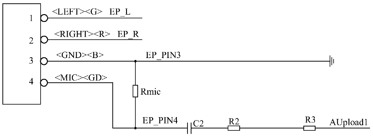
[0061] This embodiment provides a sound code communication channel circuit, Figure 10 It is a circuit structure diagram of the voice code communication channel circuit in this embodiment. like Figure 10 As shown, in this embodiment, the audio code product connector (EarphonePlus) has 4 pins, which are respectively:
[0062] Pin 1: , connect the EP_L channel;
[0063] Pin 2: , connect to EP_R channel;
[0064] Pin 3: , connect to the ground EP_PIN3 channel; and
[0065] Pin 4: , connect the voice code communication channel EP_PIN4 (in practical applications, for different standards, pins and The positions of the pins can be reversed, that is, pin 3 is pin, pin 4 is pins, such as Figure 11 shown).
[0066] In addition, the audio code communication channel EP_PIN4 is provided with an equivalent resistance R2 and a DC blocking capacitor C2. Between the effective resistor R4 and the capacitor C2) the pull-down resistor R4 is connected, and an identif...
PUM
 Abstract
Description
Claims
Application Information
 - R&D
- Intellectual Property
- Life Sciences
- Materials
- Tech Scout
- Unparalleled Data Quality
- Higher Quality Content
- 60% Fewer Hallucinations
Browse by: Latest US Patents, China's latest patents, Technical Efficacy Thesaurus, Application Domain, Technology Topic, Popular Technical Reports.
© 2025 PatSnap. All rights reserved.Legal|Privacy policy|Modern Slavery Act Transparency Statement|Sitemap|About US| Contact US: help@patsnap.com


