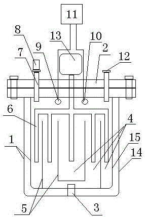
An internally heated high-pressure reactor
A high-pressure reactor and internal heating technology, applied to pressure vessels used in chemical processes, etc., can solve problems such as affecting the chemical reaction process and increasing costs
- Summary
- Abstract
- Description
- Claims
- Application Information
AI Technical Summary
Problems solved by technology
Method used
Image
Examples
Embodiment 1
[0028] Such as figure 1 As shown, an internally heated high-pressure reaction kettle includes a reaction tank composed of a reaction tank body 1 and a sealing cover 2. A single heat pipe 3 is inserted into the reaction tank from the sealing cover 2, and the diameter of the single heat pipe 3 is between 12mm- Between 15mm; single heat pipe 3 forms a temperature gradient area 4 from the center to the outer arm in the reaction tank; there is a partition 5 between the temperature gradient areas 4; there is an extension downward from the sealing cover 2 to each temperature gradient area 4 Quartz rod 7, the end of the quartz rod 7 outside the sealing cover 2 has an optical end face 12 for observation, through the optical end face 12, the reactor reaction changes in the temperature gradient area can be observed, and recorded according to the reaction time of the reactor. The reaction tank body 1 and the sealing cover 2 are sealed and connected by a flange.
Embodiment 2
[0030] Such as figure 1 As shown, an internally heated high-pressure reaction kettle includes a reaction tank composed of a reaction tank body 1 and a sealing cover 2. A single heat pipe 3 is inserted into the reaction tank from the sealing cover 2, and the diameter of the single heat pipe 3 is between 12mm- Between 15mm; single heat pipe 3 forms a temperature gradient area 4 from the center to the outer arm in the reaction tank; there is a partition 5 between the temperature gradient areas 4; there is an extension downward from the sealing cover 2 to each temperature gradient area 4 The quartz rod 7 of the quartz rod 7 outside the sealing cover 2 has an optical end face 12 for observation, and the reactor reaction change in the temperature gradient zone can be observed through the optical end face 12, and is recorded according to the reaction time of the reactor; 2. There is a stirring fork 6 extending downward toward each temperature gradient zone 4. The stirring fork 6 outs...
Embodiment 3
[0032] Such as figure 1 As shown, an internally heated high-pressure reaction kettle includes a reaction tank composed of a reaction tank body 1 and a sealing cover 2. A single heat pipe 3 is inserted into the reaction tank from the sealing cover 2, and the diameter of the single heat pipe 3 is between 12mm- Between 15mm; single heat pipe 3 forms a temperature gradient area 4 from the center to the outer arm in the reaction tank; there is a partition 5 between the temperature gradient areas 4; there is an extension downward from the sealing cover 2 to each temperature gradient area 4 The quartz rod 7 of the quartz rod 7 outside the sealing cover 2 has an optical end face 12 for observation, and the reactor reaction change in the temperature gradient zone can be observed through the optical end face 12, and is recorded according to the reaction time of the reactor; 2 There is a stirring fork 6 extending downward to each temperature gradient area 4, and the stirring fork 6 outsi...
PUM
 Abstract
Description
Claims
Application Information
 - R&D
- Intellectual Property
- Life Sciences
- Materials
- Tech Scout
- Unparalleled Data Quality
- Higher Quality Content
- 60% Fewer Hallucinations
Browse by: Latest US Patents, China's latest patents, Technical Efficacy Thesaurus, Application Domain, Technology Topic, Popular Technical Reports.
© 2025 PatSnap. All rights reserved.Legal|Privacy policy|Modern Slavery Act Transparency Statement|Sitemap|About US| Contact US: help@patsnap.com

