Cone crusher structure

A technology of cone crusher and eccentric mechanism, which is applied in the field of mining equipment, can solve problems such as easy centrifugal detachment of stop push plate, crushing load, large vibration, piston gland and oil seal falling off, etc., to increase radial stability, improve rotary Slew rate, the effect of ensuring normal operation

Active Publication Date: 2015-04-22
ZHEJIANG ZHEKUANG HEAVY IND CO LTD
View PDF6 Cites 0 Cited by
  • Summary
  • Abstract
  • Description
  • Claims
  • Application Information

AI Technical Summary

Problems solved by technology

[0003] However, existing cone crushers have the following three deficiencies: 1. The sealing effect of the hydraulic oil in the hydraulic lifting mechanism is not good, and when the hydraulic oil pressure is too high, oil leakage often occurs; 2. The hydraulic lifting mechanism The piston gland is directly fixed on the lower end surface of the piston by bolts; due to the large crushing load and vibration of the cone crusher, the piston will deflect due to vibration. When the hydraulic oil level is too low, the piston gland is directly connected to the cylinder. When the bottom cover is connected, friction between the deflection of the piston cover and the bottom cover of the cylinder body may eventually result in the breakage of the bolts fixing the piston cover, the loss of the piston cover and the oil seal, and the failure of the hydraulic lifting mechanism; 3. The supporting components include fixed The upper thrust plate at the lower end of the movable cone spindle group, the lower thrust plate fixed on the upper end surface of the piston, and the intermediate thrust plate between the upper thrust plate and the lower thrust plate, the upper and lower ends of the intermediate thrust plate They are respectively offset and matched with the upper thrust plate and the lower thrust plate; the stability of the support assembly of this structure is insufficient, and when the swing speed of the movable cone main shaft group is too fast, the stop thrust plate is easy to be separated centrifugally, and there is a hidden danger of accident

Method used


Image

  • Cone crusher structure
  • Cone crusher structure
  • Cone crusher structure

Examples


Embodiment Construction

[0018] The preferred embodiments of the present invention will be described in further detail below in conjunction with the accompanying drawings.

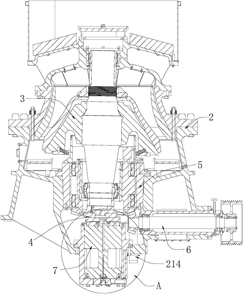
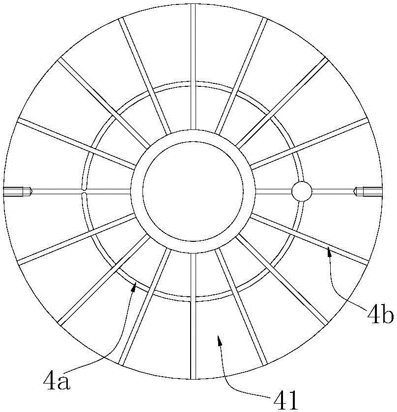
[0019] Such as Figure 1~Figure 3 The structure of the cone crusher shown includes a frame 2, and a transmission mechanism 6, an eccentric mechanism 5, a hydraulic lifting mechanism 7, a moving cone main shaft group 3 and a support assembly 4 arranged in the frame 2; the eccentric mechanism 5 and the transmission mechanism 6 are connected by transmission, the positioning of the moving cone main shaft group 3 is installed in the eccentric mechanism 5, the hydraulic lifting mechanism 7 is located under the moving cone main shaft group 3, and the hydraulic lifting mechanism 7 and the moving cone main shaft group 3 are connected through the support assembly 4.

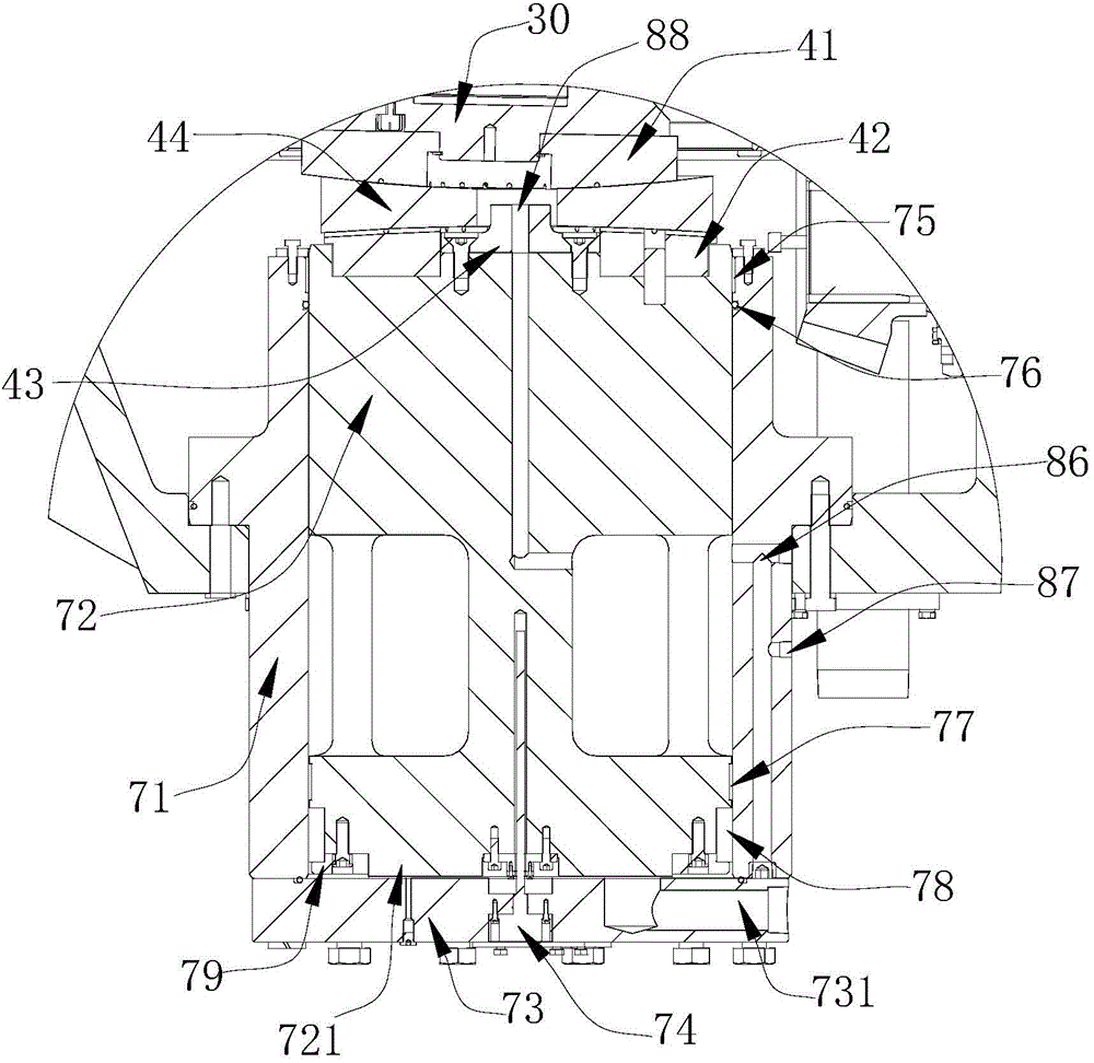
[0020] The hydraulic lifting mechanism 7 includes a hydraulic cylinder block 71, a piston 72 that can slide up and down on the hydraulic cylinder block 71, and a cylinder bott...


PUM


Abstract

The invention relates to the field of mining equipment, in particular to a cone crusher structure which comprises a machine frame, a transmission mechanism, an eccentric mechanism, a hydraulic lifting mechanism, a moving cone main shaft group and a supporting component. The transmission mechanism, the eccentric mechanism, the hydraulic lifting mechanism, the moving cone main shaft group and the supporting component are arranged in the machine frame. The eccentric mechanism is connected with the transmission mechanism in a transmission mode. The lower end of the moving cone main shaft group is arranged in the eccentric mechanism in a locating mode. The hydraulic lifting mechanism is placed below the moving cone main shaft group. The hydraulic lifting mechanism and the moving cone main shaft group are connected through the supporting component. The hydraulic lifting mechanism of the cone crusher structure is stable, uneasy to damage and good in sealing performance, and supporting component rotating swinging is stable.

Description

technical field [0001] The invention relates to the field of mining equipment, in particular to a cone crusher structure. Background technique [0002] The cone crusher is a kind of mining machinery used for crushing stones. Its principle is to squeeze and crush stones between the movable cone main shaft group and the fixed cone that rotate through the swing. Between the movable cone liner on the movable cone main shaft group and the fixed cone liner on the frame is the crushing cavity for crushing stones; and in order to crush stones of different particle sizes, the movable cone main shaft of the existing cone crusher There will be a hydraulic lifting mechanism under the group, and the hydraulic lifting mechanism is connected with the moving cone main shaft group through the support assembly; through the lifting and lowering of the piston in the hydraulic lifting mechanism, the axial height of the moving cone main shaft group is adjusted to change the size of the crushing c...

Claims


Application Information

Patent Timeline
Patent Type & Authority Applications(China)
IPC IPC(8): B02C2/04
Inventor 陈利华赵孟军李国强陈炳敏
Owner ZHEJIANG ZHEKUANG HEAVY IND CO LTD
Why Eureka
Try Eureka