Assembling and clamping device for tube sheet processing

A clamping device and tube sheet technology, applied in positioning devices, metal processing equipment, metal processing machinery parts, etc., can solve the problems of low processing efficiency and low processing accuracy, and achieve improved processing efficiency, good versatility, and alignment. effect of time reduction

Inactive Publication Date: 2015-04-22
HARBIN TURBINE
View PDF7 Cites 8 Cited by
  • Summary
  • Abstract
  • Description
  • Claims
  • Application Information

AI Technical Summary

Problems solved by technology

[0003] The purpose of the present invention is to solve the problems of low processing accuracy and low processing efficiency caused by the need to re-install and align the workpieces every time even if the existing tube sheet processing equipment processes the same group of workpieces. A clamping device for tube sheet processing

Method used


Image

  • Assembling and clamping device for tube sheet processing
  • Assembling and clamping device for tube sheet processing
  • Assembling and clamping device for tube sheet processing

Examples


specific Embodiment approach 1

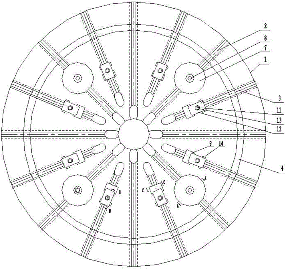
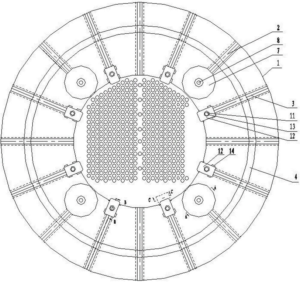
[0015] The clamping device for tube sheet processing in this embodiment, such as figure 1 , 3 , 4, and 5, its composition includes: disc table 1, a group of T-shaped grooves A (part number 2 in the figure) and a group of T-shaped grooves are arranged on the radial direction of the upper surface of the disk table 1 B (item number 3 in the figure), T-shaped groove A (item number 2 in the figure) and T-shaped groove B (item number 3 in the figure) are evenly arranged in the circumferential direction of the disc table 1, The upper surface of the disc workbench 1 is provided with a circular groove 4 in the circumferential direction on the side close to the outer edge;

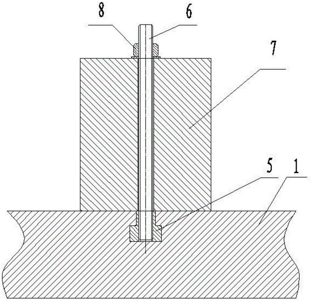
[0016] Among them, the sliding block A (the item number is 5 in the figure) is slidably installed in the T-shaped groove A (the item number is 2 in the figure), and the top of the slider A (the item number is 5 in the figure) is screwed to the double-ended screw A (the item number is shown in the figure). The part...

specific Embodiment approach 2

[0018] The difference from Embodiment 1 is that the clamping device for tube sheet processing in this embodiment, such as figure 1 , 3 , Shown in 4 and 5, the protrusion at the bottom of the equal height sliding pad 9 is located in the T-shaped groove A (the part number is 2 among the figures).

specific Embodiment approach 3

[0019] Different from the first or second specific embodiment, the clamping device for tube sheet processing in this embodiment, such as figure 1 , 3 , 4, and 5, the height of the slider A (the item number is 5 in the figure) is the same as the depth of the T-shaped groove A (the item number is 2 in the figure), and the slider A (the item number is 5 in the figure) The two opposite side surfaces and bottom surfaces with shoulders are in sliding contact with the two inner sidewalls and bottom surfaces of the T-shaped groove A (item number 2 in the figure).


PUM


Abstract

The invention relates to an assembling and clamping device for tube sheet processing. According to existing tube sheet processing equipment, even if the same set of workpieces are processed, the workpieces still need to be assembled, clamped and aligned again during each processing process, and accordingly the problems of low processing precision and low processing efficiency are caused. According to the assembling and clamping device for tube sheet processing, a set of radial T-shaped grooves A (2) and radial T-shaped grooves B (3) are evenly formed in the upper surface of a disc worktable (1) in the circumferential direction, and an annular groove (4) is formed in the side, close to the outer edge, of the disc worktable (1) in the circumferential direction; sliders A (5) are arranged in the T-shaped grooves A (2) in a sliding mode, the top of each slider A (5) is connected with a double-thread screw A (6) in a screwed mode, and each double-thread screw A (6) is sleeved with a positioning cylinder (7) in a penetrating mode; the interior of each T-shaped groove B (3) is sequentially provided with an equal-height sliding cushion block (9) and a slider B (10) in a sliding mode, the top of each slider B (10) is connected with a double-thread screw B (11) in a screwed mode, each double-thread screw B (11) is sleeved with a pressing plate (12), one end of each pressing plate (12) is located above the corresponding equal-height sliding cushion block (9) and is opposite to the corresponding equal-height sliding cushion block (9), and the other end of each pressing plate (12) is supported on the upper surface of the disc worktable (1) through a cushion block (14).

Description

technical field [0001] The invention relates to a clamping device for tube sheet processing. Background technique [0002] The tube sheet is divided into an inner tube sheet and an outer tube sheet, each of which is a group of 8. The outer circle and the position of the hole of the same group of tube sheets are consistent, but even if the existing tube sheet processing equipment processes the same group of workpieces, It is also necessary to re-align the workpiece every time it is processed to ensure that the positions of the corresponding holes are consistent, resulting in low processing accuracy, low processing efficiency, and time-consuming and laborious. Contents of the invention [0003] The purpose of the present invention is to solve the problems of low processing accuracy and low processing efficiency caused by the need to re-install and align the workpieces every time even if the existing tube sheet processing equipment processes the same group of workpieces. A c...

Claims


Application Information

Patent Timeline
IPC IPC(8): B23Q3/06
CPCB23Q3/062
Inventor 董礼涛杨庆仁马玉清王洪巍张涛车延超李军王占军
Owner HARBIN TURBINE
Why Eureka
Try Eureka