Inflating machine for injection molding of building block and inflating method using inflating machine

An aerator and block technology, which is applied in the field of building material production, can solve problems such as uneven surface, waste of steel bars in frame structure design, and reduce thermal insulation function, achieve smooth molding surface, highlight substantial features, and improve thermal insulation. heat effect

Inactive Publication Date: 2015-04-22
王长河
View PDF6 Cites 0 Cited by
  • Summary
  • Abstract
  • Description
  • Claims
  • Application Information

AI Technical Summary

Problems solved by technology

[0002] At present, in the field of construction, the outer wall or inner wall usually adopts the masonry structure of blocks (also called bricklaying), and the masonry is mostly fly ash plus blocks, which not only wastes and consumes energy, but also has Insufficient thermal insulation, light weight, heat insulation, sound insulation, etc., can not meet the requirements of the national building energy conservation. In order to solve the above problems, the hollow blocks are usually treated as follows: 1. Use polystyrene board or polyurethane board, etc. The thermal fuse is cut into small pieces and manually inserted into the hole of the hollow block. This method is costly, labor-intensive, and has poor heat insulation performance. The holes of the hollow block are tapered and the four corners have radians. Small blocks or polyurethane small blocks are very regular squares, so there must be gaps around the small boards, as long as there are gaps, air circulation will be generated to reduce the heat insulation function; 2. Pour foamed cement into the holes of the hollow blocks, this The cost of the method is high, the labor intensity is high, the output is low, the surface is not uniform, and the dry density is large, which will cause waste of steel bars in the design of the frame structure; heat, but left a great potential safety hazard, the entire concrete protective layer is hung outside the structural column by the polystyrene board during masonry, it is difficult to ensure that the concrete protective layer will not fall off when the polystyrene board degrades and cause accidents; 4. Inject light materials such as polystyrene particles or polyurethane particles into the holes of the hollow block. In this patent, polystyrene particles are used as an example. This method can better solve the above problems, but most of them are artificially made of polystyrene particles. The particles are filled into the holes of the blocks, and then steam is passed into the holes of the blocks, the efficiency is low, the molding is poor, and the heat preservation effect is not ideal
The patent application number 201310401916.3 discloses a block injection molding machine and its use method. In this patent, steam is injected into the completely closed space formed by the steam delivery head, the fixed mold box and the lower template through the steam pipeline through the steam delivery head. The steam instantly penetrates into the hole of the block with polyphenylene particles, making the polyphenylene particles pre-expanded and enlarged again (because the hole space of the block remains unchanged, the polystyrene particles are extruded and condensed) and condense together to form a whole with the block. Using this kind of steam entraining device, during the process of entraining, the polyphenylene particles in the upper layer of the block hole first contact with the steam and become larger instantly, making it difficult for the steam to enter the bottom layer of the block hole, resulting in the polyphenylene particles in the bottom layer of the block hole It is difficult for the particles to re-foam and become larger, and there are large gaps between the polystyrene particles, which makes it difficult for the processed blocks to achieve better thermal insulation effects

Method used


Image

  • Inflating machine for injection molding of building block and inflating method using inflating machine
  • Inflating machine for injection molding of building block and inflating method using inflating machine
  • Inflating machine for injection molding of building block and inflating method using inflating machine

Examples


specific Embodiment approach 2

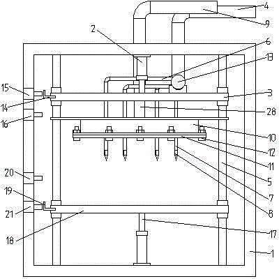
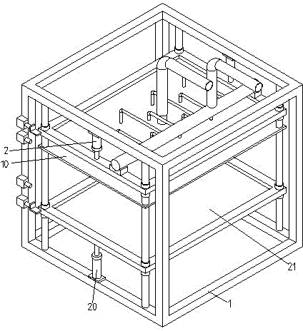
[0066] In this example, if Figure 8As shown, the gas storage box 10 and the filling needle 7 are all fixed, as Figure 6 As shown, the gas filling needle 7 is connected to the gas storage pipe 13 through the rigid connecting pipe 6 , the gas storage pipe 13 is fixed above the gas storage box 10 , and the gas storage box 10 is fixed on the guide column 5 .

[0067] The gas filling operation in this embodiment has the following methods:

[0068] (1) Place the block injected with polystyrene particles on the block platform 18, and the cylinder II 17 drives the block upward so that the block is pushed against the rubber plate 11 under the air storage box, and at the same time makes the block hole and the gas filling needle 7 Corresponding to the position of the air filling hole I, the air filling needle 7 is inserted into the interior of the polystyrene particles in the hole of the block for internal gas filling, and then the upper surface of the hole of the block is filled with...


PUM


Abstract

The invention discloses an inflating machine for injection molding of a building block. The inflating machine comprises a rack and a power device I used for driving the building block to move up and down, wherein an inflating device is arranged on the rack, and comprises a building block hole interior inflating device and a building hole upper surface inflating device. The inflating machine for the injection molding of the building block is provided with the interior inflating device and the upper surface inflating device, polyphenyl granules expand due to influence of steam, and are adhered and cured to form an integral polyphenyl block which is tightly matched with the wall of a hollow building block, the interior inflating device can be used for inflating high-temperature steam to the interiors of the polyphenyl granules of holes of the building block so that the polyphenyl granules in the middles and the bottoms of the holes of the building block well expand, and are well adhered and cured; upper surfaces of the polyphenyl granules of the holes of the building block are inflated and pressurized by using the upper surface inflating device, so that the polyphenyl granules at the upper layers of the holes of the building block well expand, and are well adhered and cured, and thus a formed surface is flat, and the heat insulation effect of the building block is effectively improved.

Description

technical field [0001] The invention relates to the technical field of building material production, in particular to an air dispenser for block injection molding. Background technique [0002] At present, in the field of construction, the outer wall or inner wall usually adopts the masonry structure of blocks (also called bricklaying), and the masonry is mostly fly ash plus blocks, which not only wastes and consumes energy, but also has Insufficient thermal insulation, light weight, heat insulation, sound insulation, etc., can not meet the requirements of the national building energy conservation. In order to solve the above problems, the hollow blocks are usually treated as follows: 1. Use polystyrene board or polyurethane board, etc. The thermal fuse is cut into small pieces and manually inserted into the hole of the hollow block. This method is costly, labor-intensive, and has poor heat insulation performance. The holes of the hollow block are tapered and the four corner...

Claims


Application Information

Patent Timeline
Patent Type & Authority Applications(China)
IPC IPC(8): B29C45/17
CPCB29C45/1704
Inventor 王长河
Owner 王长河
Why Eureka
Try Eureka