
Thermal printing head for automatically removing carbon deposits and manufacturing method

A technology of a thermal print head and a manufacturing method, applied in directions such as printing, can solve the problems of shallow depth, small width of groove 6a, etc.

Active Publication Date: 2016-10-19
SHANDONG HUALING ELECTRONICS
View PDF5 Cites 1 Cited by
  • Summary
  • Abstract
  • Description
  • Claims
  • Application Information

AI Technical Summary

Problems solved by technology

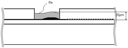
[0006] In the product of the aforementioned patent document 1, the width of the groove 6a is small, the depth is shallow, and a large amount of carbon deposits are buried in the groove 6a, and the step difference of the groove disappears, which cannot pass through the crimping of the recording medium, and sufficient tape carbon build-up problem
[0007] In addition, the product recorded in Patent Document 2 first grinds the first protective layer 31 with low hardness, and then the second protective film 32 with high hardness forms a flat structure on the first protective film 31, but it has nothing to do with carbon deposition (recording medium) Records related to loss and powder falling during printing)

Method used


Image

  • Thermal printing head for automatically removing carbon deposits and manufacturing method
  • Thermal printing head for automatically removing carbon deposits and manufacturing method
  • Thermal printing head for automatically removing carbon deposits and manufacturing method

Examples


Embodiment Construction

[0020] The patent of the present invention will be further described below in conjunction with examples:

[0021] Embodiment 1

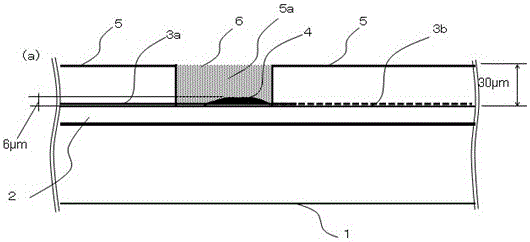
[0022] The thermal print head includes a substrate made of insulating material, a base layer (underglaze glass) is made on the substrate, and then lead electrodes are formed on the surface of the substrate and the base layer. The lead electrodes are divided into individual electrodes and common electrodes, which are formed on the lead electrodes The heating resistor belt along the main printing direction, one end of the individual electrode is connected to the heating resistor belt in the secondary printing direction, the other end is connected to the control IC, and one end of the common electrode is connected to the heating resistor belt in the secondary printing direction. One end is connected with the wire pattern, the above part constitutes the substrate ceramic circuit, and the ceramic circuit and the PCB constitute the entire electrical part, and t...


PUM


Abstract

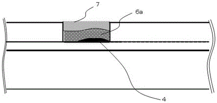
The invention relates to a thermo-sensitive printing head, in particular to a thermo-sensitive printing head for automatic deposited carbon removal and a manufacturing method. The thermo-sensitive printing head for automatic deposited carbon removal comprises a ceramic substrate with ground glaze, several lead electrodes, common lead electrodes and a protrusion-shaped heating body formed in the main scanning direction, wherein the several lead electrodes and the common lead electrodes are formed on the substrate, the heating body is used as a center to stick dry films at the positions different distances away from the center position in the auxiliary scanning direction, and a deep grove is formed in the upper portion of the heating body. Two layers of glass frit is coated in the groove, a grinding layer is formed after glass sintering, very steep segment difference is formed at the end of the grinding layer after grinding planarization, and protective films are formed on the grinding layer and the lead electrodes. The thermo-sensitive printing head is characterized in that the grinding layer is arranged at the upper portion of the heating body, the grinding layer is subjected to planarization treatment, the paper outlet side, namely the common lead electrode side, is longer, the large segment difference is formed at the end of the grinding layer, produced paper scraps are effectively pushed from the heating body to the position of the segment difference by means of the structure, and the thermo-sensitive printing head can automatically remove deposited carbon.

Description

Technical field [0001] The patent of the present invention relates to a thermal printing head, in particular to a printing head with a flattened structure of the protrusions of the heating element and effectively eliminating the influence of carbon deposits and a manufacturing method thereof. Background technique [0002] As we all know, the thermal print head includes a substrate made of insulating material, a base layer (underglaze glass) is made on the substrate, and then lead electrodes are formed on the surface of the substrate and the base layer. The lead electrodes are divided into individual electrodes and common electrodes, on the lead electrodes The heating resistor strip formed along the main printing direction, one end of the individual electrode is connected to the heating resistor strip along the secondary printing direction, the other end is connected to the control IC, and one end of the common electrode is connected to the heating resistor strip along the secondar...

Claims


Application Information

Patent Timeline
Patent Type & Authority Patents(China)
IPC IPC(8): B41J2/335
Inventor 张东娜孙华刚远藤孝文魏洪修朱丽娜
Owner SHANDONG HUALING ELECTRONICS
Learn More