
Carbon dioxide flooding well head oil collection tank

A carbon dioxide, oil collecting tank technology, applied in chemical instruments and methods, containers, packaging, etc., can solve the problems of condensation, easy pollution of oil and gas leakage, safety valve failure, etc., to avoid environmental pollution, avoid oil and gas resources loss, shock mitigation effect

Active Publication Date: 2017-03-22
PETROCHINA CO LTD +2
View PDF3 Cites 0 Cited by
  • Summary
  • Abstract
  • Description
  • Claims
  • Application Information

AI Technical Summary

Problems solved by technology

[0003] The present invention aims to overcome the environmental protection problems that the oil wells intermittently produce a large amount of associated gas such as carbon dioxide in the background technology when the conventional oil collection tank is used, the safety valve is prone to failure or the safety problem of condensation, and the oil gas leaks and the environment is easy to pollute, and provides a CO2 flooding well head oil collection tank

Method used


Image

  • Carbon dioxide flooding well head oil collection tank
  • Carbon dioxide flooding well head oil collection tank
  • Carbon dioxide flooding well head oil collection tank

Examples


Embodiment Construction

[0015] The present invention will be further described below in conjunction with specific embodiment:

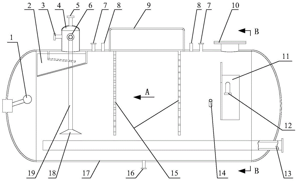
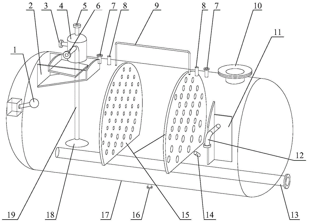
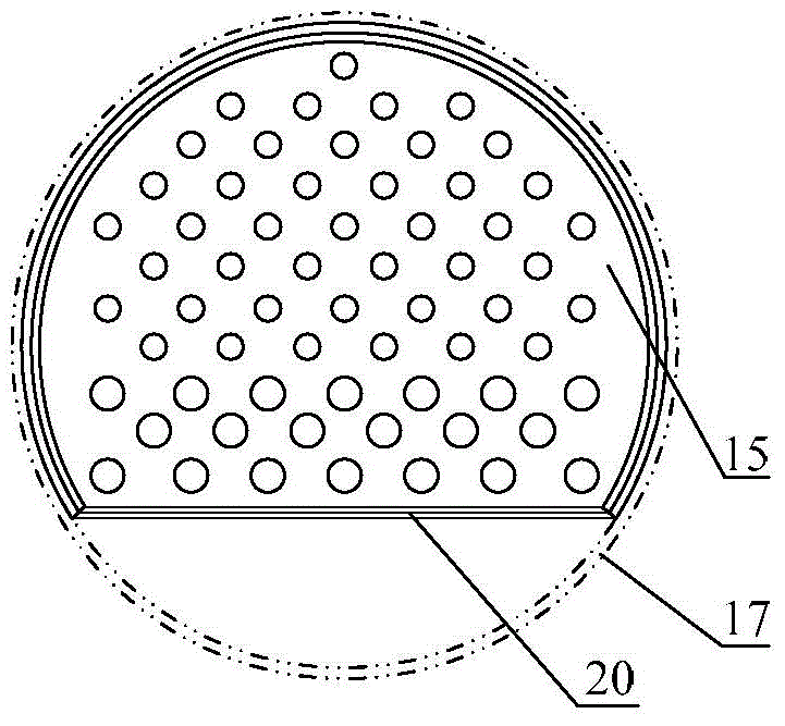
[0016] attached figure 1 to combine figure 2 , image 3 , Figure 4 As shown, the wellhead oil collection tank of the carbon dioxide flooding well includes a horizontal container 17 and an electric heating tube 13. The inner wall of the container 17 is pierced with a medium inlet 12 near the right head side, and the end of the medium inlet 12 is opposite to the angular medium inlet. Baffle plate 11, the height of the medium inlet baffle plate 11 is the radius of the container’s axial section circle, the oil-gas two-phase mixed medium enters the oil collection tank and first impacts the angular medium inlet baffle plate, and the angular baffle plate faces away from the gas-liquid phase outlet, which can Increase the flow path of the gas-liquid phase medium, increase the time of gas-liquid phase sedimentation and separation without increasing the volume of the oil collecti...


PUM


Abstract

The invention relates to a wellhead oil collecting tank of a carbon dioxide flooding well, and aims at solving the problems that the gas-liquid separation effect is poor, a safety valve is frequently opened, and associated gas carrying a certain amount of crude oil leaks to the outside when the general oil collecting tank is used under the condition that a large amount of carbon dioxide and other associated gases are discontinuously produced by the flooding well, and resulting the failure of the safety valve or condensed block to influence the safety. The wellhead oil collecting tank of the carbon dioxide flooding well is characterized in that an angular medium inlet baffle (11) is arranged at an end head of a medium inlet (12); first- to second-order pore plates (15) are vertically connected between the medium inlet baffle (11) and a liquid outlet pipe (19) along the radial section; a pressure balance pipe (9) is arranged at the upper part of a container; a two-grade baffle plates (2) are arranged at an inlet of a gas distributing manifold (4). With the adoption of the wellhead oil collecting tank of the carbon dioxide flooding well, the impact of a large amount of carbon dioxide and other associated gases discontinuously produced by the flooding well to the gas-liquid separating capacity of a device can be reduced, so that the separating effect can be ensured, the safety of the device can be improved, and the environmental pollution can be avoided.

Description

technical field [0001] The invention relates to a wellhead oil collection tank in the technical field of oil and gas gathering and transportation in oil and gas fields, in particular to a wellhead oil collection tank for carbon dioxide flooding wells. Background technique [0002] Carbon dioxide flooding is a relatively new oilfield development technology, which can not only achieve effective development of oilfields, but also is more suitable for low-permeability, special-permeability, water-sensitive reservoirs and other occasions where water injection and chemical agent injection are difficult to achieve effective development. , and a large amount of carbon dioxide used for oil displacement is buried underground, which is conducive to low-carbon environmental protection, and it can be said to serve multiple purposes. In recent years, it has just begun to be applied in my country's oilfield development. At present, in the process flow of the surface gathering and transpor...

Claims


Application Information

Patent Timeline
Patent Type & Authority Patents(China)
IPC IPC(8): B01D17/022B65D88/06B65D90/00
CPCB65D88/54B65D90/34B65D90/48
Inventor 孟岚刘学王梓栋谈庆旬于海波黄延强王林
Owner PETROCHINA CO LTD
Learn More