A bead punching seat structure of a bead nailing machine

A technology of bead flushing seat and bead nailing machine, which is applied in the decoration of textiles, textiles and papermaking, etc. It can solve the problems of high processing and installation costs, generation of defective products, mixed beads with small diameters, etc., and save processing and installation costs , low processing and installation costs, simple and reasonable structure

Inactive Publication Date: 2017-01-11
林尧宇
View PDF4 Cites 0 Cited by
  • Summary
  • Abstract
  • Description
  • Claims
  • Application Information

AI Technical Summary

Problems solved by technology

[0008] 1. The structure is complex, the structure of the seat body of the ball flushing seat and the heavy block is not easy to process, the installation accuracy of the heavy block is relatively high, and the processing and installation costs are relatively high;
[0009] 2. The noise is high. Every punching of the stamping rod will hit the weighted block, resulting in a hard collision noise. In the process of automatic recovery of the weighted block, under the action of gravity, the other end of the weighted block will hit the blocking rod. Another hard collision noise is generated, which makes the beading environment noisy and unpleasant;
[0010] 3. Since the bead nailing machine is a machine with high frequency of use, the number of beads nailed by the bead nailing machine per minute is as high as 150-300. From this calculation, the heavy weight block is hit twice every time the beads are nailed, and it is hit in one minute. The number of hard collisions is 150-300×2 equal to 300-600 times, so the overweight block is easy to wear and deform, and the service life is relatively short;
[0011] 4. Since the beading machine has a high frequency of beading per minute, and the beading machine is manually operated, this requires the operator to have quick eyesight and quick hands, and constantly move the position of the clothes to beaded. Sometimes the clothes are not on the beading machine. If it is not flat, the clothing will be hooked on the heavy weight during the process of moving the clothes and clothing, resulting in the unsmooth beading process, and the beading will deviate from the position, resulting in defective products, which need to be modified and increase the workload of the operator;
The specifications of the beads for each beading are generally uniform, but beads of a certain specification batch may be mixed with some beads with small diameters, and the weighted block of the structure of the bead flushing seat in the prior art cannot verify the size of the beads. All will be supported, so that some beads smaller than a certain diameter are nailed to the clothes, resulting in defective products

Method used


Image

  • A bead punching seat structure of a bead nailing machine
  • A bead punching seat structure of a bead nailing machine
  • A bead punching seat structure of a bead nailing machine

Examples


Embodiment 1

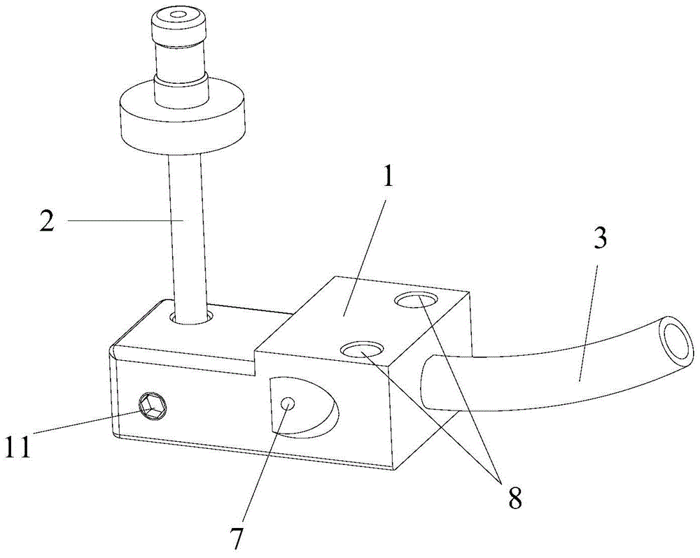
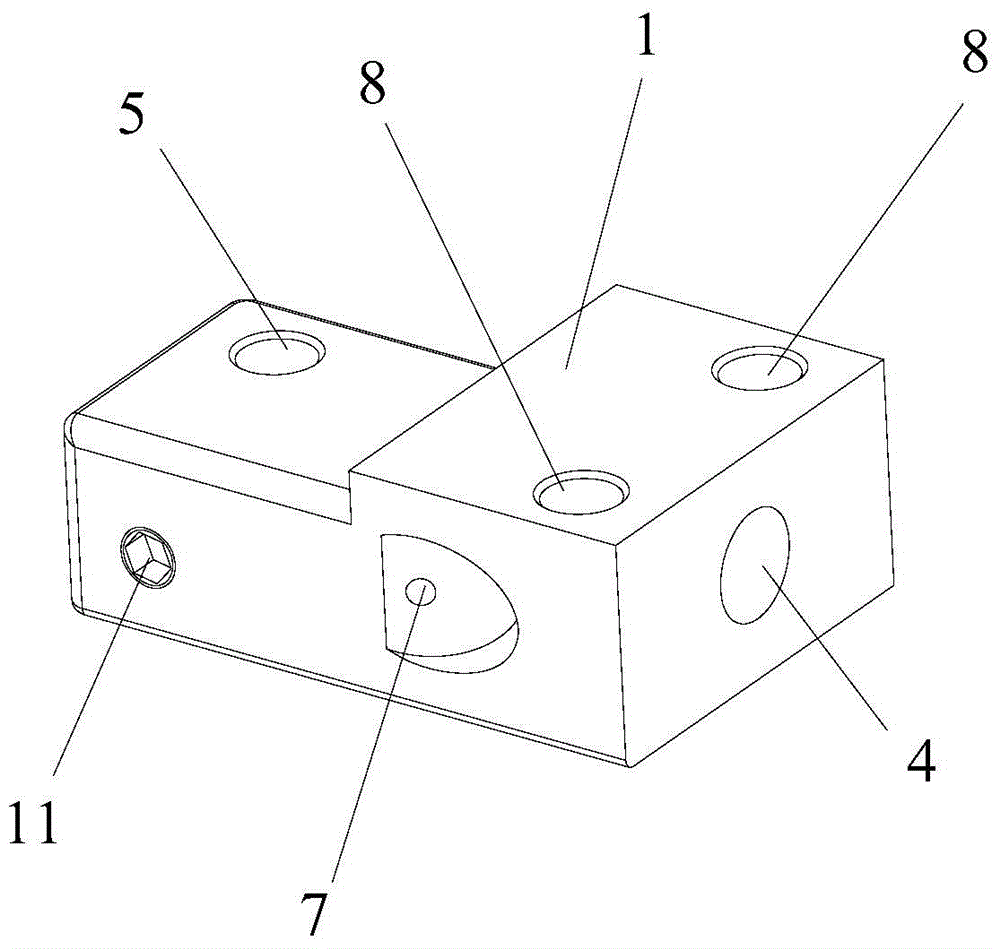
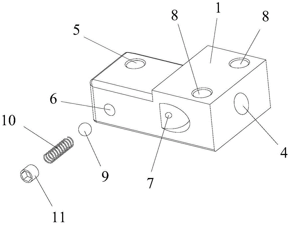
[0043] See Figure 1-Figure 6 , figure 1 It is the overall structure diagram of the bead punching seat structure of the bead nailing machine in Embodiment 1 of the present invention, and the bead channel and punching rod are also included in the figure; figure 2 It is the overall structural diagram of the structure of the beading seat of the bead nailing machine in Embodiment 1 of the present invention; image 3 It is an exploded structure diagram of the structure of the beading seat of the bead nailing machine in Embodiment 1 of the present invention; Figure 4 It is a top view structure diagram of the structure of the bead punching seat of the bead nailing machine in Embodiment 1 of the present invention; Figure 5 for Figure 4 The cross-sectional structure diagram of A-A direction in the middle; Image 6 for Figure 4 The cross-sectional structure diagram of the B-B direction in the middle.

[0044] The bead punching seat structure of the bead nailing machine provid...

Embodiment 2

[0062] The bead punching seat structure of the bead nailing machine provided by the embodiment of the present invention includes a seat body, and a bead inlet hole and a punching hole provided on the seat body.

[0063] The entrance of the bead hole is set on the outer wall of the seat body, the outlet of the bead hole is set on the inner wall of the punching hole, the bead hole is connected with the bead channel, the beads enter from the entrance of the bead hole, and the bead hole is connected to the outlet of the bead hole After coming out, it enters the punching hole. The punching hole vertically passes through the upper and lower surfaces of the seat body, and the punching rod moves up and down in the punching hole to punch down the beads and nail them together with the button.

[0064] The seat body is also provided with a pressing hole, and the outlet of the pressing hole is arranged on the inner hole wall of the punching hole. There are balls, springs and locking piece...


PUM


Abstract

The invention discloses a bead stamping base structure of a bead nailing machine. A stamping hole perpendicularly penetrates through the upper surface and the lower surface of a base body, an inlet of a bead inlet hole is formed in the outer wall of the base body, an outlet of the bead inlet hole is formed in the inner hole wall of the stamping hole, the base body is provided with an abutting hole, an outlet of the abutting hole is formed in the inner hole wall of the stamping hole, a bead, a spring and a locking part are arranged in the abutting hole, the locking part locks the spring and the bead in the abutting hole, the spring abuts against the bead, the diameter of the bead is greater than that of the outlet of the abutting hole, the bead protrudes out of the outlet of the abutting hole, and part of the bead is exposed in the stamping hole. Compared with the prior art, the bead stamping base structure of the bead nailing machine is simple and reasonable in structure, low in machining and installation cost, low in bead nailing noise, and capable of reducing abrasion and prolonging service life, clothes will not be hooked in the bead nailing process, the machining process is smooth, beads smaller than bead nailing specifications will be checked out, and inferior-quality products are reduced.

Description

technical field [0001] The invention relates to the field of bead nailing machines, in particular to a bead flushing seat structure of the bead nailing machine. Background technique [0002] Nowadays, with the development of the clothing industry, people are increasingly pursuing the beauty and diversity of clothing. In addition to the requirements for the style of clothing itself, there are also requirements for accessories attached to clothing, so it is necessary to bind some on the clothing. Accessories such as diamonds, beads or plastic hardware buttons can enhance the taste and added value of clothing. In the present application, clothing has a broad meaning and is not limited to clothes and trousers, but also includes footwear, hats, gloves, handbags, and the like. [0003] At first, the original beading operation was done by manual threading, which was very inefficient. Later, the beading machine was developed slowly, and it was changed to mechanized beading. Bead n...

Claims


Application Information

Patent Timeline
Patent Type & Authority Patents(China)
IPC IPC(8): D06Q1/10
CPCD06Q1/10
Inventor 不公告发明人
Owner 林尧宇
Why Eureka
Try Eureka