Full-automatic water drainage slide valve

A fully automatic, sliding valve technology, applied in the petrochemical field, can solve the problems of poor operation reliability, high labor intensity, waste of the environment, etc., to ensure stability and reliability, increase the effective use volume, and increase the effect of settling time.

Active Publication Date: 2015-04-22
XI'AN PETROLEUM UNIVERSITY
View PDF10 Cites 0 Cited by
  • Summary
  • Abstract
  • Description
  • Claims
  • Application Information

AI Technical Summary

Problems solved by technology

This method is labor-intensive for workers, and it is difficult to accurately control when releasing water. Oil products are often discharged together with bottom water, causing waste and environmental pollution, and also increasing the workload of sewage treatment.
One is a water cutter that uses the structure of the buoy lever as the principle for automatic drainage. The mechanical structure of this water cutter is relatively complicated, the mechanical transmission line is long, the efficiency is low, and the operation reliability is poor.
The main disadvantage is that the bottom water cannot be fully automatically discharged to the set amount at one time, or the electric automatic control water cutter needs to provide additional power, and because there are electrical components, there are potential safety hazards, so the application is seldom
[0003] At present, there are also some designs and patents called oil tank automatic drainage devices at home and abroad. In the technical field of oil storage tank drainage devices, several automatic or semi-automatic oil storage tank drainage devices have been developed at home and abroad. The utility model patent (patent application number: 200920310310.8) of "automatic drainer for oil tank", the utility model patent (patent a

Method used


Image

  • Full-automatic water drainage slide valve
  • Full-automatic water drainage slide valve
  • Full-automatic water drainage slide valve

Examples


Embodiment Construction

[0034] The present invention will be further described below in conjunction with embodiment.

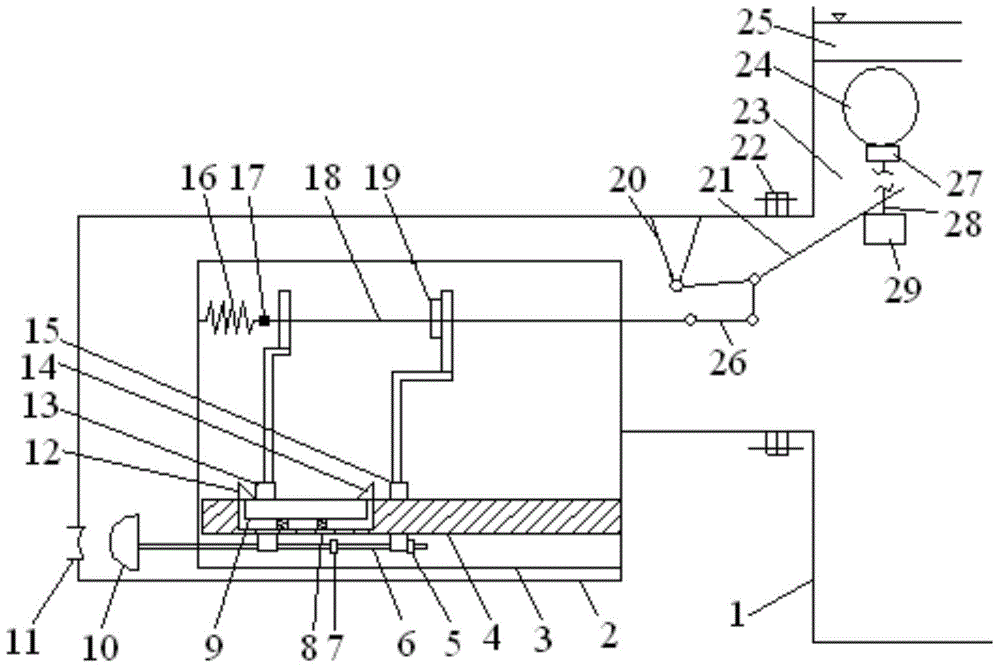
[0035] see figure 1 , the present invention includes an outer valve sleeve 2 fixedly arranged at the bottom water outlet of the oil tank 1, the outer valve sleeve 2 is fixedly connected with the oil tank 1 through a flange 22, the outer valve sleeve 2 communicates with the oil tank 1, and the outer valve sleeve 2 A valve 11 for outputting bottom water is arranged on the top, an inner valve sleeve 3 is fixed inside the outer valve sleeve 2, and the inner valve sleeve 3 is airtight, and a guide frame 4 is fixedly installed inside the inner valve sleeve 3, and the upper guide frame 4 corresponds to the A left sliding sleeve 13 and a right sliding sleeve 15 are provided, and both the left sliding sleeve 13 and the right sliding sleeve 15 can move on the guide frame 4;

[0036] A groove is provided on the guide frame 4, and a spring 8 is arranged in the groove. One end of the spring 8 is...


PUM


Abstract

The invention discloses a full-automatic water drainage slide valve. The full-automatic water drainage slide valve aims at achieving the effects that bottom water can be thoroughly discharged, self closing in the water drainage process is avoided, and water level adjustment on a drain valve can be achieved according to different storage media. According to the technical scheme, the full-automatic water drainage slide valve comprises an outer valve sleeve, the outer valve sleeve is communicated with an oil tank, an inner valve sleeve is fixedly arranged in the outer valve sleeve and is closed, a guide support is fixedly arranged in the inner valve sleeve, and a left sliding sleeve and a right sliding sleeve are arranged on the guide support and can be moved on the guide support. A guide rod is arranged at the lower end of the guide support in the axial direction and is fixedly connected with the left sliding sleeve, the guide rod and the right sliding sleeve are connected in the mode of being capable of relatively sliding, one end of the guide rod extends out of the inner valve sleeve, and a valve cover is fixedly arranged at the extending end of the guide rod. A connecting rod is arranged at the upper end of the left sliding sleeve and the upper end of the right sliding sleeve, a tension spring is connected with one end of the connecting rod, and the other end of the connecting rod extends out of the inner valve sleeve and is connected with one end of a control lever, and the other end of the control rod extends into the oil tank; a floating ball is arranged in the oil tank, and a control block is arranged at the lower end of the floating ball.

Description

technical field [0001] The invention belongs to the field of petrochemical technology and relates to a mechanical device, in particular to a fully automatic drain slide valve. Background technique [0002] As a container for storing crude oil or other petroleum products, oil tanks are widely used in refineries, oil fields, oil depots and other industries. The drainage system of the oil tank is an indispensable accessory equipment. If the bottom water in the oil tank cannot be discharged in time, it will not only reduce the utilization rate of the oil tank, but also cause corrosion to the tank part, which will affect the service life of the oil tank. At present, the bottom discharge methods in oil storage mainly include the following methods: one is to manually open the water cutting valve at regular intervals to discharge the accumulated water inside. This method is labor-intensive for workers, and it is difficult to accurately control when releasing water. Oil products ar...

Claims


Application Information

Patent Timeline
IPC IPC(8): F16K3/30F16K31/02
CPCF16K31/24F16K31/523
Inventor 康勇
Owner XI'AN PETROLEUM UNIVERSITY
Why Eureka
Try Eureka