
Electric heating tube testing device and method

A testing device and testing method technology, applied in the direction of measuring devices, instruments, etc., can solve the problems of uninterrupted heat loss, large contact area between water surface and air, unable to reach 100 ℃ water temperature test, etc. handy effect

Active Publication Date: 2015-04-22
XINYI HUIMEI ELECTRICAL APPLIANCES +1
View PDF9 Cites 5 Cited by
  • Summary
  • Abstract
  • Description
  • Claims
  • Application Information

AI Technical Summary

Problems solved by technology

[0003] At present, there are many types of electric heating tubes, but there is no comprehensive testing device that can effectively test the safety performance of electric heating tubes.
The current safety performance testing methods of electric heating pipes and corresponding disadvantages are as follows: 1. When measuring water pressure, install the electric heating pipe products on the electric water heater, conduct daily tap water pressure test, and accept it without leaking water, without testing its safety indicators ;2. When measuring the water temperature of 100°C, put the electric heating tube in an ordinary container. The safety index of the test is generally tested between 95°C and 99°C. The data is not accurate, because the container is not sealed, the contact area between the water surface and the air Large, continuous loss of heat, unable to reach 100 ℃ water temperature test; 3. The constant test method is not used in the oil temperature test, and the water injection heating test is used; 4. The sealing device test is not used in the air pressure test

Method used


Image

  • Electric heating tube testing device and method

Examples


Embodiment 1

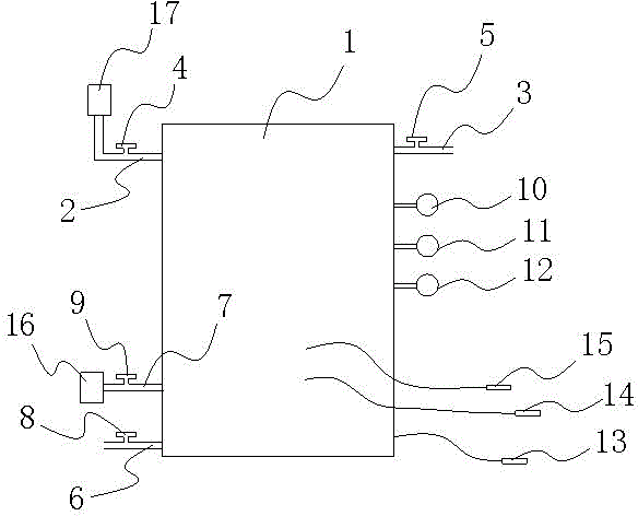
[0020] As shown in the figure (the cover is not shown in the figure), the electric heating tube testing device of this embodiment includes a metal test cylinder 1 with a movable cylinder cover, and the upper part of the test cylinder 1 is connected with a liquid inlet pipe 2 and an exhaust gas. Pipe 3, the liquid inlet pipe 2 is provided with a liquid inlet valve 4, and the exhaust pipe 3 is provided with an exhaust valve 5; the bottom of the test tube 1 is provided with a liquid discharge pipe 6 and an air intake pipe 7, and the liquid discharge pipe 6 is provided with a liquid discharge valve 8, and the air inlet pipe 7 is provided with an air inlet valve 9; the test cylinder 1 is connected with an air pressure gauge 10, a hydraulic pressure gauge 11, and a temperature gauge 12 through pipelines, and the cylinder body of the test cylinder 1 is passed through a wire The ground terminal 13 is connected, and the test cylinder 1 is provided with a withstand voltage test terminal ...


PUM


Abstract

The invention aims at providing an electric heating tube testing device and method. The electric heating tube testing device and method are used for comprehensively and reliably testing the safety performance of electric heating tubes. The electric heating tube testing device comprises a metal testing barrel with a movable barrel cover. The upper portion of the testing barrel is connected with a liquid inlet pipe and an air exhaust pipe. The liquid inlet pipe is provided with a liquid inlet valve. The air exhaust pipe is provided with an air exhaust valve. The lower portion of the testing barrel is provided with a liquid outlet pipe and an air inlet pipe. The liquid outlet pipe is provided with a liquid outlet valve. The air inlet pipe is provided with an air inlet valve. The testing barrel is connected with an air pressure gauge, a hydraulic pressure gauge and a temperature gauge through pipelines. The barrel body of the testing barrel is connected with an earth terminal through a wire. The testing barrel is provided with a testing terminal communicated with the interior and the exterior of the testing barrel. The electric heating tube testing device is applicable to testing of various electric heating tubes, the electric heating tube testing method is convenient to implement, reliable and reliable, and factory testing of the electric heating tubes can be achieved.

Description

technical field [0001] The invention belongs to the technical field of electric heating tube testing, and in particular relates to an electric heating tube testing device and a testing method thereof. Background technique [0002] The electric heating tube (tubular electric heating element) is made of a metal tube (including stainless steel and copper tube), and the spiral electric heating alloy wire (nickel-chromium, iron-chromium alloy) is uniformly distributed along the central axis of the tube, and the gap is filled and compacted with good insulation Magnesia sand with thermal conductivity, and the two ends of the nozzle are sealed with silica gel. This electric heating tube can heat air, metal molds and various liquids. [0003] At present, there are many kinds of electric heating tubes, but there is no comprehensive testing device that can effectively test the safety performance of electric heating tubes. The current safety performance testing methods of electric heat...

Claims


Application Information

Patent Timeline
IPC IPC(8): G01D21/02
Inventor 王广宁谢博松王焮灏方园梁宏鉴
Owner XINYI HUIMEI ELECTRICAL APPLIANCES
Learn More