
Test bed for brake noise of high-speed train brake disc

A technology for noise testing and high-speed trains, applied in railway vehicle testing and other directions, can solve the problems of noise reduction, no high-speed train brake disc braking noise, noise pollution along the line, etc., and achieve the effect of reducing braking noise.

Inactive Publication Date: 2015-04-22
SOUTHWEST JIAOTONG UNIV
View PDF13 Cites 11 Cited by
  • Summary
  • Abstract
  • Description
  • Claims
  • Application Information

AI Technical Summary

Problems solved by technology

[0002] When a high-speed train is braking, the relative rotation of the brake disc and the brake pad produces braking noise, which affects the comfort of passengers and generates noise pollution along the line.
At present, noise pollution is mainly reduced by installing sound barriers along the line, and there are few ways to reduce noise by reducing noise sources.
In order to reduce brake noise from the source, it is necessary to use special test equipment to test and analyze the relationship between the material, structure, interface characteristics, train speed, load and other factors of the brake disc and brake pad and the noise, but so far there is no high-speed brake noise. Special test equipment for brake noise of train brake discs

Method used


Image

  • Test bed for brake noise of high-speed train brake disc

Examples


Embodiment

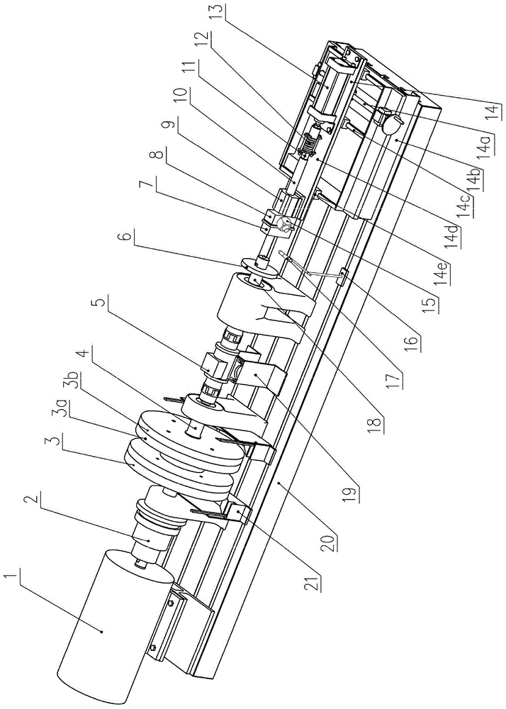
[0024] figure 1 Shown is a brake noise test bench for brake discs of high-speed trains. Its structural features are: a variable frequency motor 1 is installed on the left side of the base 20, and the output shaft of the variable frequency motor 1 passes through an electromagnetic clutch 2, a flywheel shaft 4, and a torque sensor in sequence. 5 is connected with the brake shaft 18; the right end of the brake shaft 18 is connected with the brake disc 6, the flywheel group 3 is fixed on the flywheel shaft 4, and the torque sensor 5 is fixed on the base 20 through the sensor base 19;

[0025] The right side of base 20 is equipped with slide table 14 that can move back and forth, and cylinder 13 is installed on the right side of slide table 14; The clamp 8 holding the brake pad 7 is connected; the middle part of the guide rod 10 is supported on the slide table 14 through the linear bearing 9; the side of the clamp 8 is equipped with a three-dimensional acceleration sensor 15;

[0...


PUM


Abstract

The invention relates to a test bed for brake noise of a high-speed train brake disc. According to constitution of the test bed, an output shaft of a variable frequency motor on the left side of a base is connected with a brake shaft sequentially through an electromagnetic clutch, a fly wheel shaft and a torque sensor, the brake disc is connected with the right end of the brake shaft, and a fly wheel set is fixed to the fly wheel shaft; a sliding table capable of moving front and back is arranged on the right side of the base, an air cylinder is installed on the right side of the sliding table, an output shaft at the left end of the air cylinder is connected with a clamp for clamping a brake pad sequentially through a spring, a piezoelectric type one-way force sensor and a guide rod, and the middle of the guide rod is supported on the sliding table through a linear bearing; a three-dimensional acceleration sensor is installed on the side face of the clamp, the left face of the brake pad is opposite to the right face of the brake disc, the induction end of a sound sensor is located nearby the brake disc, and the variable frequency motor, the electromagnetic clutch and the air cylinder are electrically connected with a control system. The test bed can simulate the brake working condition of the high-speed train brake disc to carry out brake noise tests, find out the relationship among the brake working condition, brake materials and the brake noise and provide a test basis for reducing the brake noise of the high-speed train brake disc.

Description

technical field [0001] The invention belongs to the technical field of brake noise testing of high-speed train brake discs. Background technique [0002] When a high-speed train is braking, the relative rotation of the brake disc and the brake pad produces braking noise, which affects the comfort of passengers and generates noise pollution along the line. At present, noise pollution is mainly reduced by installing sound barriers along the line, and there are few ways to reduce noise by reducing noise sources. In order to reduce brake noise from the source, it is necessary to use special test equipment to test and analyze the relationship between the material, structure, interface characteristics, train speed, load and other factors of the brake disc and brake pad and the noise. Special test equipment for brake noise of train brake discs. Contents of the invention [0003] The purpose of the present invention is to provide a brake noise test bench for brake discs of high-...

Claims


Application Information

Patent Timeline
IPC IPC(8): G01M17/08
Inventor 莫继良盖小红罗大兵黄清健陈光雄朱旻昊周仲荣
Owner SOUTHWEST JIAOTONG UNIV
Learn More