Hatless brake rotor

a brake rotor and hatless technology, applied in the field of brake systems, can solve problems such as the potential for noise generation during braking, and achieve the effects of reducing brake pulsation, reducing braking noise, and improving air cooling

Inactive Publication Date: 2005-12-01
GENERAL MOTORS COMPANY
View PDF7 Cites 8 Cited by
  • Summary
  • Abstract
  • Description
  • Claims
  • Application Information

AI Technical Summary

Benefits of technology

[0009] The present invention is a hatless rotor for an automotive disk brake system, wherein the following improvements are realized over known disk brake systems: reduced braking noise, improved air cooling, decoupling of wheel to rotor cross-talk, reduced brake pulsation, reduced mass, reduced rotor cheeks temperature during braking, and better air movement access for improved cooling of the rotor cheeks.

Problems solved by technology

One disadvantage of disk brakes is the potential for generation of noise during braking.

Method used


Image

  • Hatless brake rotor
  • Hatless brake rotor
  • Hatless brake rotor

Examples


Embodiment Construction

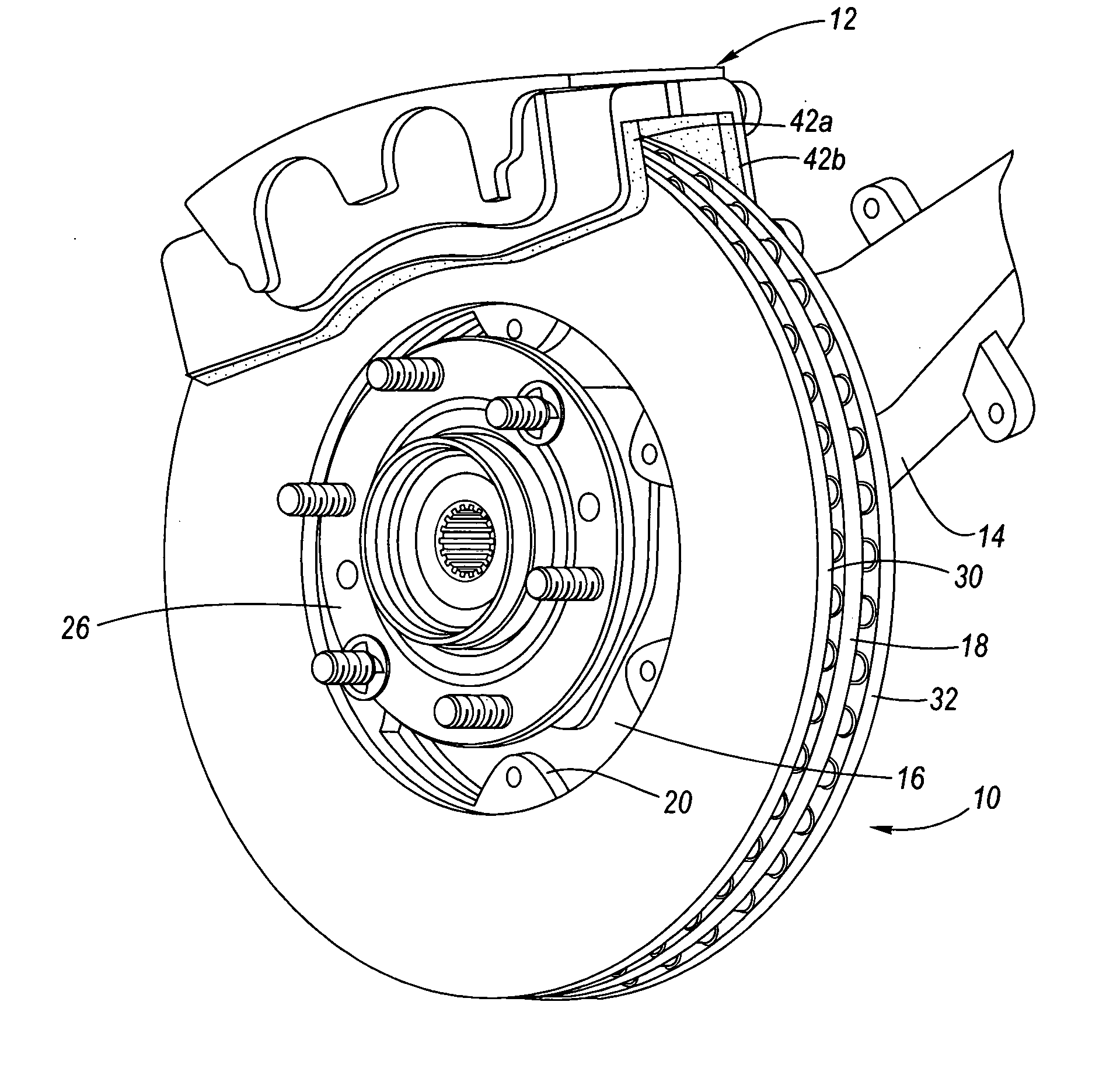
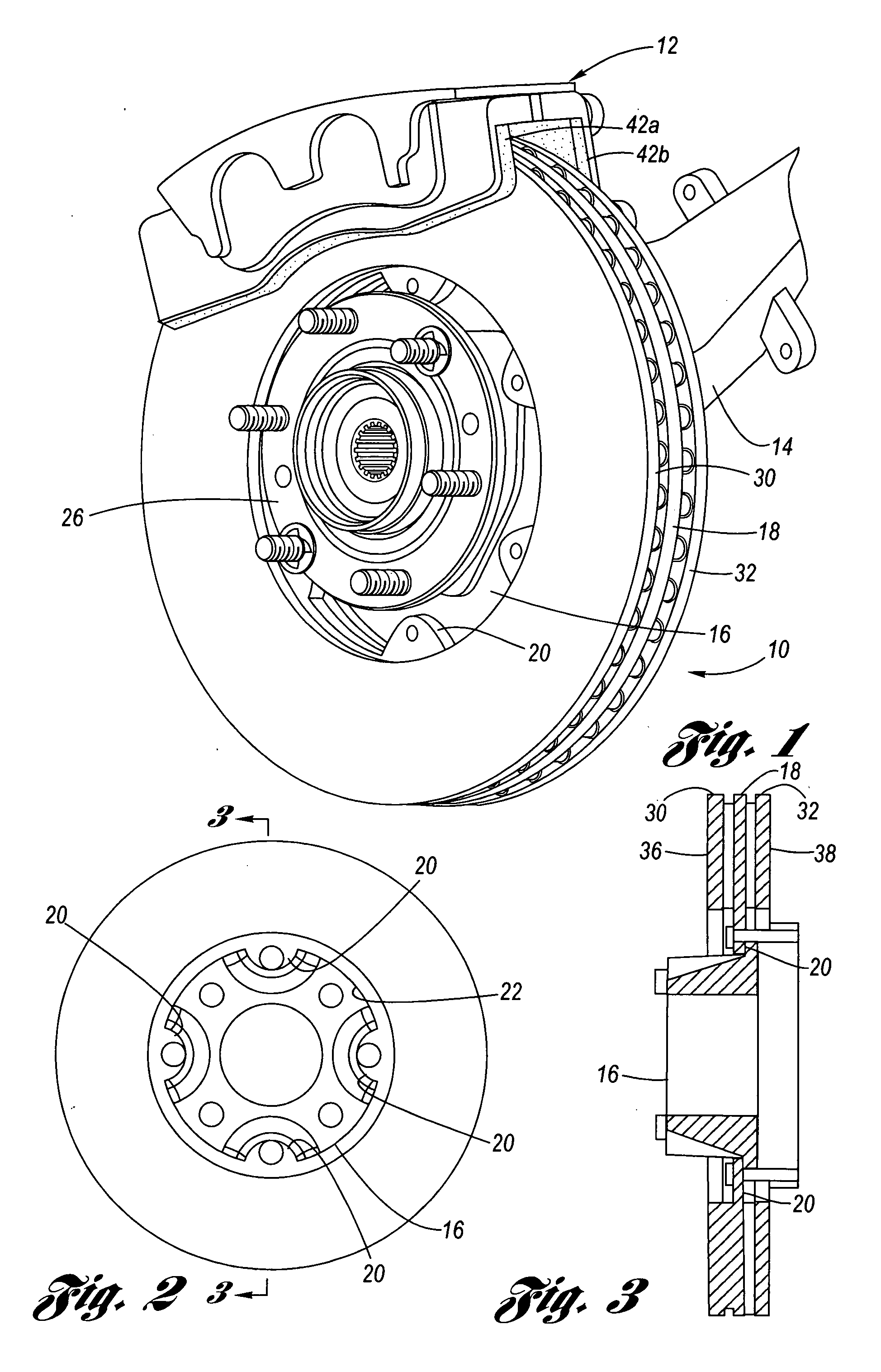
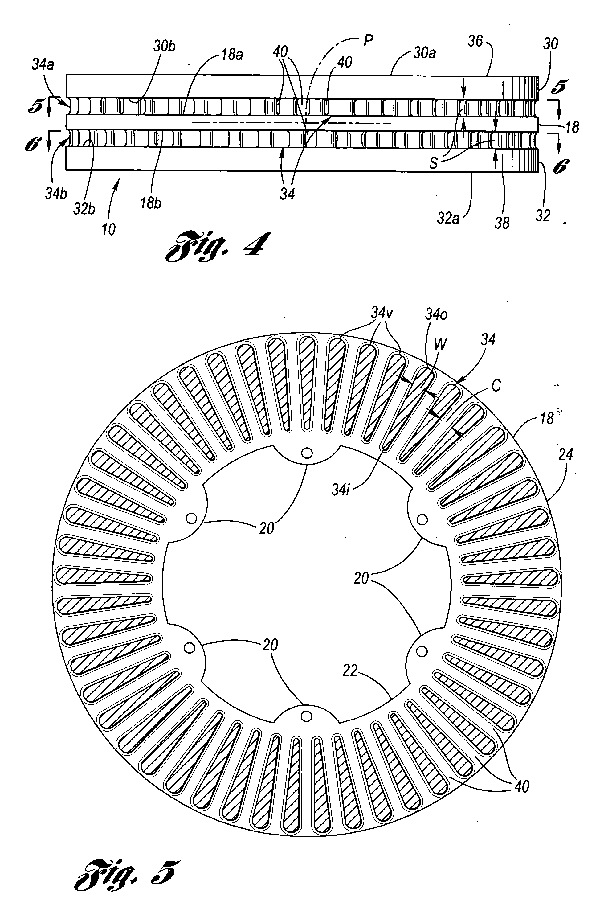
[0024] Referring now to the Drawing, FIGS. 1 through 3 depict various aspects of a preferred example of a hatless rotor 10 according to the present invention which is operatively integrated with a disk brake system 12 of a motor vehicle at a wheel location thereof. The axle 14 has an axle hub (not visible) to which is directly connected a rotor hub 16. The rotor hub 16 is, in turn, connected to an annularly shaped central disk 18 of the hatless rotor 10, via a plurality of mounting tabs 20 (by way of example six mounting tabs are shown in FIGS. 1, 5 and 7 and four mounting tabs are shown with the hatless rotor of FIG. 2) which are located at an inner rotor perimeter 22, and on the central plane P (see FIG. 4), of the hatless rotor. It will be seen that since the hatless rotor 10 is mounted directly to the axle hub via the rotor hub 16, that the wheel hub 26 connects directly to the axle hub independently of the direct connection of the hatless rotor to the axle hub. This feature iso...


PUM


Abstract

A hatless rotor for an automotive disk brake system, wherein the following improvements are realized over known disk brake systems: reduced braking noise, improved air cooling, decoupling of wheel to rotor cross-talk, reduced brake pulsation, reduced mass, reduced rotor cheeks temperature during braking, and better air movement access for improved cooling of the rotor cheeks. The hatless rotor includes a first rotor cheek, a second rotor cheek and a central disk, wherein the first and second rotor cheeks are spaced from, and mutually interconnected to, the central disk by first and second sets of vanes, staggered relative to each other, and configured to provide optimal air circulation. The central rotor disk is connected directly to the motor vehicle axle hub via a suitable rotor hub connected thereto.

Description

TECHNICAL FIELD [0001] The present invention relates to braking systems used for motor vehicle applications, and more particularly to motor vehicle disk brake systems. Still more particularly, the present invention relates to a hatless rotor for a motor vehicle disk brake system, featuring double rotor cheeks, constant cross-sectional area air passages, and staggered vanes. BACKGROUND OF THE INVENTION [0002] Motor vehicle disk brake systems utilize, at each wheel, a “rotor” connected to an axle hub of a rotatable axle of the motor vehicle, and an opposing set of selectively movable brake pads connected to a non-rotating component of the motor vehicle. The rotor includes a disk shaped rotor “cheek” having opposing brake pad engagement surfaces, wherein when braking is to occur, the braking system causes the brake pads to press upon respective brake pad engagement surfaces of the rotor cheek. Frictional interaction between the rotating rotor cheek and non-rotating brake pads causes br...

Claims


Application Information

Patent Timeline
Patent Type & Authority Applications(United States)
IPC IPC(8): F16D65/00F16D65/10F16D65/12
CPCF16D65/0006F16D2065/1356F16D2065/1328F16D65/123
Inventor ZAHDEH, AKRAM R.
Owner GENERAL MOTORS COMPANY
Why Eureka
Try Eureka