Method for testing gravity driving two-phase fluid loops compatibility
A fluid circuit and gravity-driven technology, applied in the field of spacecraft thermal control, can solve the problems that non-condensable gas cannot be tested directly, and achieve the effect of simple and feasible filling method, fast test method and convenient judgment
Active Publication Date: 2015-04-22
BEIJING INST OF SPACECRAFT SYST ENG
View PDF5 Cites 2 Cited by
- Summary
- Abstract
- Description
- Claims
- Application Information
AI Technical Summary
Problems solved by technology
[0007] (2) The noncondensable gas generated in the
Method used
View moreImage
Smart ImageViewing Examples
Examples
 PUM
 Abstract
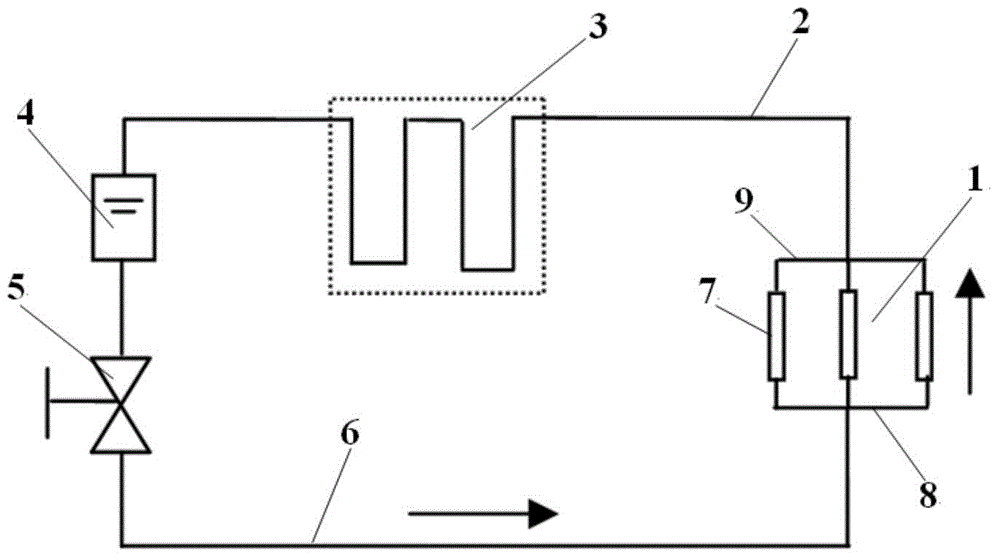
The invention discloses a method for testing gravity driving two-phase fluid loops compatibility. The method can effectively simulate a decomposition process of a gravity driving two-phase fluid loop ammonia working medium under high temperature by taking nickel as a catalyst, and can determine the compatibility of the gravity driving two-phase fluid loops. According to the invention, an equivalent simulation test member is employed for simulating the decomposition process of the gravity driving two-phase fluid loop ammonia working medium on the day period, non-condensable gas amount generated by the gravity driving two-phase fluid loop ammonia working medium on the day period can be measured by directly employing a gravity heat pipe non-condensable gas test method, compatibility of the gravity driving two-phase fluid loops can be conveniently determined, and the test method is fast and convenient.
Description
Login to View More Claims
Login to View More Application Information
Patent Timeline
 Owner BEIJING INST OF SPACECRAFT SYST ENG
Features
- R&D
- Intellectual Property
- Life Sciences
- Materials
- Tech Scout
- Unparalleled Data Quality
- Higher Quality Content
- 60% Fewer Hallucinations
Learn More Browse by: Latest US Patents, China's latest patents, Technical Efficacy Thesaurus, Application Domain, Technology Topic, Popular Technical Reports.
© 2025 PatSnap. All rights reserved.Legal|Privacy policy|Modern Slavery Act Transparency Statement|Sitemap|About US| Contact US: help@patsnap.com


