
Five-dimensional dynamic stereoscopic clutter map implementation method based on DDR3-SDRAM

A technology of DDR3-SDRAM and an implementation method, which is applied to radio wave measurement systems, instruments, etc., can solve the clutter environment that cannot be suppressed by ground objects and weather clutter, the resolution of clutter map is not high, and the detection performance of radar is reduced. Adaptability and other issues to achieve the effect of fast access and block processing

Active Publication Date: 2015-04-22
CNGC INST NO 206 OF CHINA ARMS IND GRP
View PDF2 Cites 8 Cited by
  • Summary
  • Abstract
  • Description
  • Claims
  • Application Information

AI Technical Summary

Problems solved by technology

The 3D clutter map divides the detection range of the radar into several distance / azimuth / elevation area units. Compared with the traditional clutter map, the 3D clutter map can distinguish between high and low altitude areas. The establishment of a full-frequency channel clutter map cannot effectively suppress ground clutter and meteorological clutter; on the other hand, the three-dimensional clutter map is not fine enough to divide the clutter areas within the radar detection range, and the clutter power estimation The method adopts the method of intra-pulse distance unit averaging and inter-pulse correlation accumulation, so the resolution of the clutter map is not high, which leads to insufficient suppression of ground clutter and meteorological clutter by some multi-beam radars and three-coordinate radars Sufficient, thereby reducing the detection performance of the radar and the adaptability to the clutter environment

Method used


Image

  • Five-dimensional dynamic stereoscopic clutter map implementation method based on DDR3-SDRAM
  • Five-dimensional dynamic stereoscopic clutter map implementation method based on DDR3-SDRAM
  • Five-dimensional dynamic stereoscopic clutter map implementation method based on DDR3-SDRAM

Examples


Embodiment Construction

[0035] Now in conjunction with embodiment, accompanying drawing, the present invention will be further described:

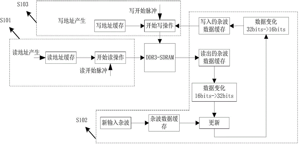
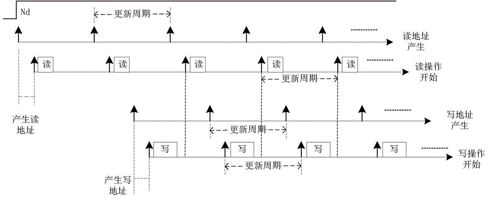
[0036] This embodiment utilizes the DDR3-SDRAM implementation method to complete the read and write control of the DDR3-SDRAM through the FPGA to realize a five-dimensional dynamic three-dimensional clutter map, including the following steps: (a) perform a read operation on the DDR3-SDRAM, and read out the clutter wave data; (b) use the recursive filter to update the clutter map, and perform data conversion processing; (c) rewrite the updated clutter data to the corresponding position of DDR3-SDRAM, complete the update of the clutter map, and establish Clutter diagram.

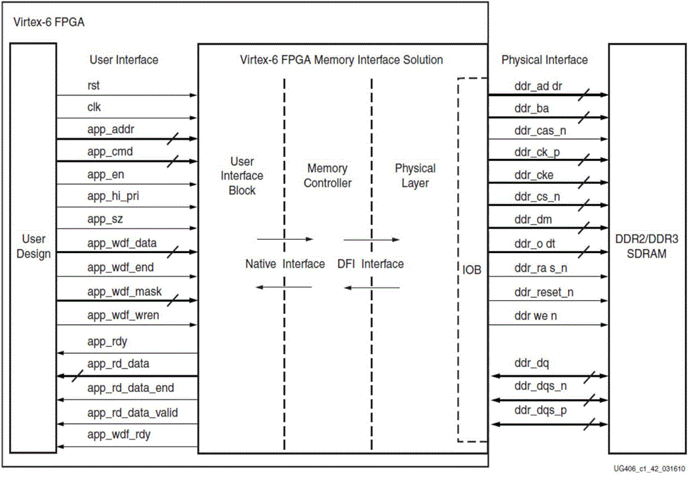
[0037] The invention is realized by using the FPGA on a certain radar digital signal processing board to read and write the external DDR3-SDRAM. The main device in the digital signal processing board is an FPGA-XC6VLX240T of a Xilinx company and a DSP-TMS320C6416 of a TI company, two DDR3-SDRAMs...


PUM


Abstract

The invention relates to a five-dimensional dynamic stereoscopic clutter map implementation method based on a DDR3-SDRAM. According to the five-dimensional dynamic stereoscopic clutter map implementation method, reading and writing control over the DDR3-SDRAM is achieved through an FPGA, and then a five-dimensional dynamic stereoscopic clutter map is established. The method comprises the following steps that (a) reading operation is conducted on the DDR3-SDRAM, and clutter data are read out; (b) a clutter map is updated through a recursive filter, and data conversion is conducted; (c) the updated cluster data are rewritten to the corresponding position of the DDR3-SDRAM, updating of the cluster map is completed, and a clutter map is established. Compared with a traditional cluster map implementation method, the five-dimensional dynamic stereoscopic clutter map implementation method based on the DDR3-SDRAM is characterized in that a clutter area is finely divided, and besides traditional distance division, direction division and pitching division, a PRF mode and clutters of a full-Doppler channel are also divided. Clutter data are specially processed, the storage capacity of the clutter map is doubled.

Description

technical field [0001] The invention belongs to the field of digital signal processing in array radar signal processing, and relates to target detection of clutter images. It specifically relates to a DDR3-SDRAM-based five-dimensional dynamic clutter map implementation method, using DDR3-SDRAM to establish a five-dimensional three-dimensional dynamic clutter map, five-dimensional for azimuth, pitch, distance, Doppler channel and PRF mode. Background technique [0002] The clutter map is a clutter intensity distribution map stored in the memory within the range of radar power. It is a technology for detecting moving targets with extremely low Doppler frequencies or suppressing clutter. With the development of large-scale integrated circuits and modern radar With the development of radar, the research of clutter diagram has been paid more and more attention by radar design workers. [0003] The modern radar signal processing system largely works on the clutter. It records the...

Claims


Application Information

Patent Timeline
Patent Type & Authority Applications(China)
IPC IPC(8): G01S7/41
CPCG01S7/021
Inventor 王辉辉袁子乔辛海涛杨刚岳三创刘翔
Owner CNGC INST NO 206 OF CHINA ARMS IND GRP
Learn More