Projection system and adjusting method for emergent light of laser pen in projection system

A technology of projection system and adjustment method, which is applied in the directions of optics, nonlinear optics, and electric-operated teaching aids. It can solve problems such as low brightness, reduced laser pointer guidance effect, and large light spot, and achieve the effect of improving the use effect.

Active Publication Date: 2015-04-22
BOE TECH GRP CO LTD
View PDF10 Cites 3 Cited by
  • Summary
  • Abstract
  • Description
  • Claims
  • Application Information

AI Technical Summary

Problems solved by technology

[0004] When the angle formed by the laser pointer and the screen is in some extreme angle range or the distance between the screen and the screen is far away, the light projected by the laser pointer will form a large spot on the screen and the brightness is low, which will reduce the laser pointer. The guiding effect of

Method used


Image

  • Projection system and adjusting method for emergent light of laser pen in projection system
  • Projection system and adjusting method for emergent light of laser pen in projection system
  • Projection system and adjusting method for emergent light of laser pen in projection system

Examples


Embodiment 1

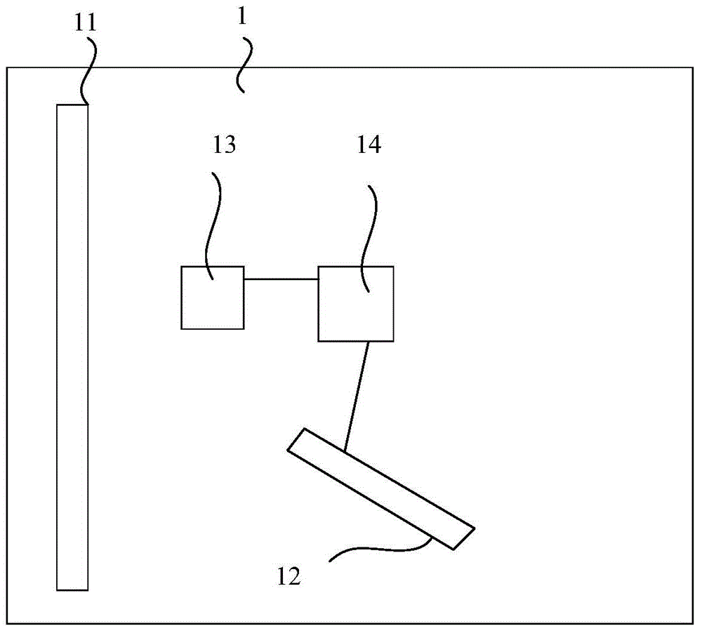
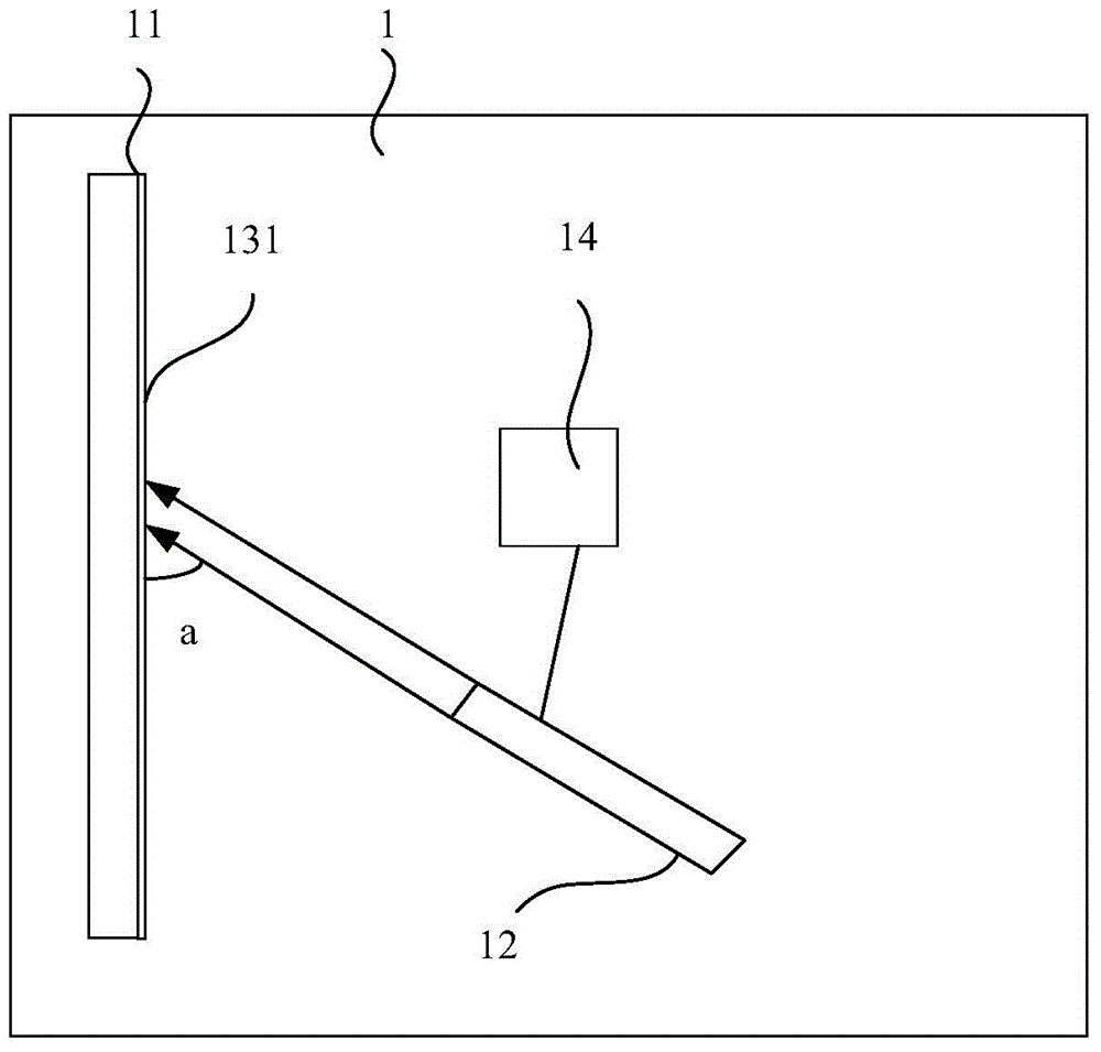
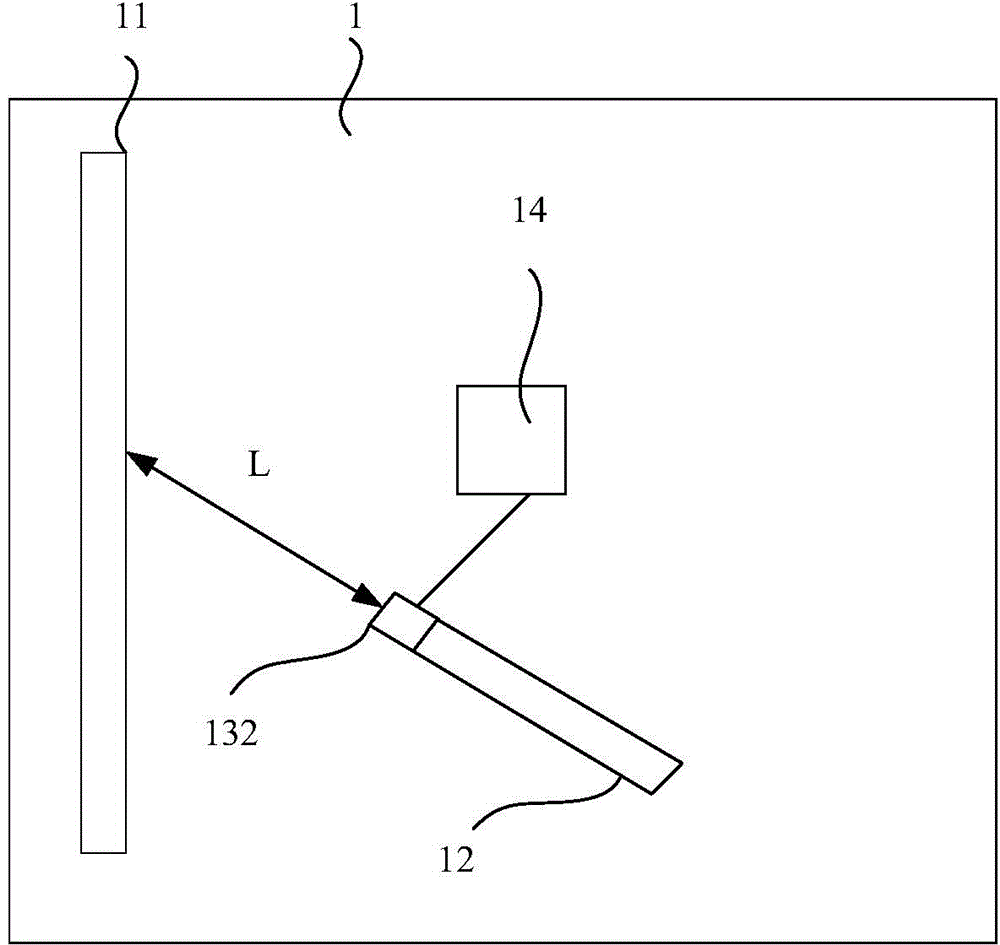
[0042] Such as figure 1 as shown, figure 1 The schematic structural diagram of the first projection system provided by the embodiment of the present invention; the present invention provides a projection system 1, including: a projector (not shown in the figure), a screen 11 and a laser pointer 12, and also includes:

[0043] The position detection device 13 is used to detect the actual position information of the laser pointer 12 relative to the display surface of the screen 11;

[0044]The control device 14 connected with the signal of the position detection device 13 is used to compare the actual position information detected by the position detection device 13 with the preset standard position information range, and adjust the laser pointer when the actual position information exceeds the standard position information range. The diameter and brightness of the light spot formed by projecting the light emitted by 12 on the display surface of the screen 11 are respectively w...

Embodiment 2

[0058] Such as Figure 5 as shown, Figure 5 The flow chart of the method for adjusting the emitted light of the laser pointer in the projection system provided by the embodiment of the present invention; the present invention also provides a method for adjusting the emitted light of the laser pointer in the projection system mentioned in the first embodiment above, include:

[0059] Step S501: Detect the actual position information of the laser pointer relative to the display surface of the screen;

[0060] Step S502: According to the comparison between the received actual position information and the preset standard position information range, when the actual position information exceeds the standard position information range, adjust the light emitted by the laser pointer to project the light spot formed on the display surface of the screen The diameter and brightness of are respectively within the preset diameter threshold and brightness threshold of the light spot.


PUM


Abstract

The invention provides a projection system and an adjusting method for emergent light of a laser pen in the projection system. The adjusting method is used for adjusting the size and the brightness of light spots formed by projecting light emitted by the laser pen on a screen so as to improve the use effect of the laser pen. The projection system comprises a position detecting device and a control device, wherein the position detecting device is used for detecting actual position information of the laser pen relative to a display face of the screen, and the control device is connected with the position detecting device through signals and used for comparing the actual position information detected by the position detecting device with a preset standard position information range, and adjusting the emergent light of the laser pen to make the diameter and the brightness of the light spots formed by projecting the light on the display face of the screen be correspondingly located in a preset diameter threshold value and a preset brightness threshold value of the light spots respectively when the actual position information exceeds the standard position information range.

Description

technical field [0001] The invention relates to the field of display technology, in particular to a projection system and a method for adjusting the emitted light of a laser pointer in the projection system. Background technique [0002] Currently, presentations (Powerpoint, PPT) are widely used in education, speeches, conferences, and the like. During the presentation, the projection system mainly includes: a projector, a screen and a laser pointer. During the presentation of the PPT, the laser pointer, as a striking moving spot, can point the PPT at a long distance and remind the audience to watch the important information. [0003] In the actual application of the laser pointer, the use state of the laser pointer is: the distance between the laser pointer and the screen is within the range, and the light emitted by the laser pointer is vertically irradiated on the screen. If the angle formed by the laser pointer and the screen deviates from the vertical angle, the diamet...

Claims


Application Information

Patent Timeline
Patent Type & Authority Applications(China)
IPC IPC(8): G03B21/00G03B21/14G02F1/29G09B5/02G09B17/02
CPCG02F1/29G03B21/00G03B21/142G09B5/02G09B17/02G02F1/294
Inventor 王博武乃福
Owner BOE TECH GRP CO LTD
Why Eureka
Try Eureka