Method for determining load effect of wind-wave coupling design of long-span bridge structure

A load effect and bridge structure technology, applied in calculation, special data processing applications, instruments, etc., can solve problems such as low efficiency, achieve the effect of improving calculation efficiency and reducing calculation amount

Active Publication Date: 2015-04-22
ZHEJIANG UNIV +1
View PDF1 Cites 15 Cited by
  • Summary
  • Abstract
  • Description
  • Claims
  • Application Information

AI Technical Summary

Problems solved by technology

However, the statistical calculation of the ultimate load effect of structural design including dynamic effects requires a large number of structural dynamic

Method used


Image

  • Method for determining load effect of wind-wave coupling design of long-span bridge structure
  • Method for determining load effect of wind-wave coupling design of long-span bridge structure
  • Method for determining load effect of wind-wave coupling design of long-span bridge structure

Examples


Embodiment Construction

[0027] The present invention will be further described below in conjunction with drawings and embodiments.

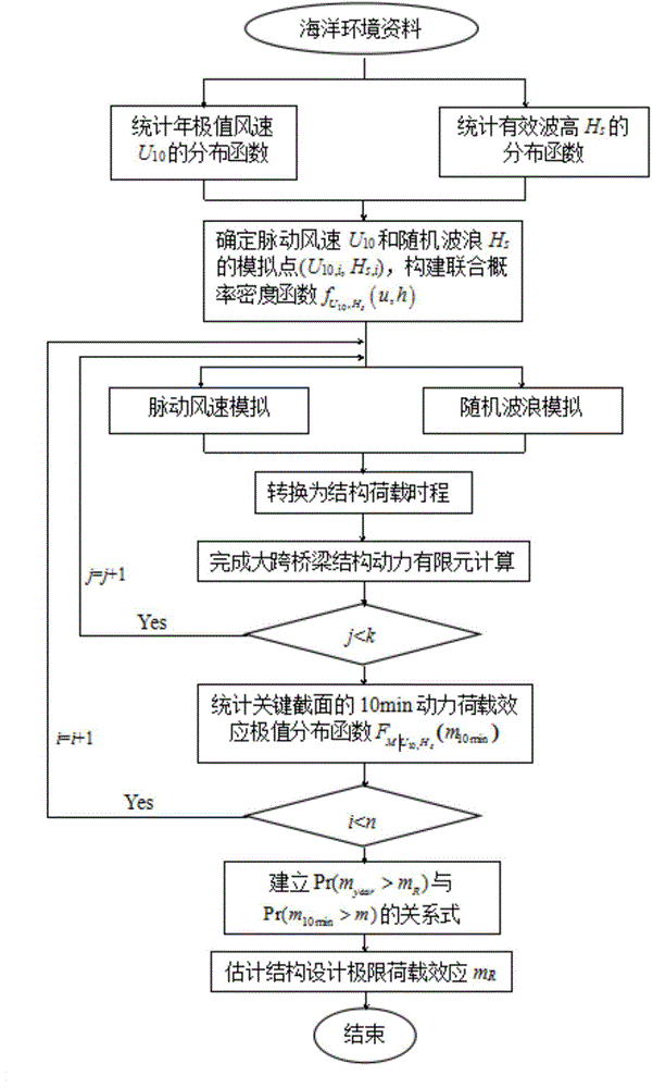
[0028] The invention provides a method for determining the wind-wave coupling design load effect of a long-span bridge structure, the process of which is as follows figure 1 As shown, the method includes the following steps:

[0029] (1) According to the annual extreme wind speed U 10 and significant wave height H s Observation value sequence, count the distribution functions of the two respectively, where U 10 、H s Both obey the Gumbel distribution:

[0030] F ( u ) = exp [ - exp ( - u - μ u σ n ) ] - - - ...


PUM


Abstract

The invention provides a method for determining load effect of a wind-wave coupling design of a long-span bridge structure. The method is an improved load effect determination method. One-dimensional distribution of a structure dynamic load effect extremum replaces two-dimensional joint distribution of a wind and wave environment element extremum, so that design ultimate load effect under the condition of recurrence interval is estimated according to an extremum exceedance probability distribution rule of 10-minute dynamic load effect of the structure. The method comprehensively employs a finite element modelling technology, Monte Carlo numerical modeling, a threshold method (POT), generalized Pareto distribution (GPD) and a bayes formula; for the key section of the structure, the acquired design ultimate load effect takes the dynamic characteristics of the structure into account and further conforms to the reality, so that the wind-wave coupling design of the structure is more reliable.

Description

technical field [0001] The invention belongs to the field of structural design of sea-crossing bridges, and relates to a method for determining the design load effect, in particular to a method for estimating a given weight under the coupling action of wind and waves by the extreme value of the 10-minute dynamic load effect of a long-span bridge structure exceeding the probability distribution law A method for designing ultimate load effects under current conditions. Background technique [0002] Determining structural design criteria for complex marine environments is necessary for large sea-crossing bridge structures and other similar structures. Traditional methods consider that environmental elements such as wind and waves are independent of each other, and the structural design load under a given return period condition is the combination of the design loads of each element under the return period. Obviously, this method ignores the mutual coupling between wind and wav...

Claims


Application Information

Patent Timeline
IPC IPC(8): G06F17/50
Inventor 黄铭枫涂志斌楼文娟宋建永
Owner ZHEJIANG UNIV
Why Eureka
Try Eureka