
Multi-level system architecture for massive independent equipment data flow

A technology of independent equipment and system architecture, applied in transmission systems, special data processing applications, electrical components, etc., can solve the problems of high development cost, inaccessible data, and it is difficult for independent equipment to achieve distributed acquisition, and achieve high-performance computing capabilities , to achieve the effect of processing power

Inactive Publication Date: 2015-04-22
TONGFANG SHENZHEN CLOUD COMPUTING TECH
View PDF2 Cites 3 Cited by
  • Summary
  • Abstract
  • Description
  • Claims
  • Application Information

AI Technical Summary

Problems solved by technology

The existing solutions are oriented to the on-site LAN, cannot support Internet applications, and can only realize the release of monitoring screens to the Internet, especially for factory production lines. The existing solutions have the following defects:
[0003] 1. It is difficult to support random addition of devices
[0004] 2. Facing the original point, it cannot effectively distinguish the equipment
[0005] 3. When applied to tens of thousands of independent devices, the cost of implementation and development from collection to application is extremely high, and the variability is extremely weak
[0006] 4. For the plant-level scale, it is difficult to effectively expand capacity and performance in the face of a large number of independent equipment data. It can only be achieved by deploying multiple real-time databases. However, multiple real-time databases are not connected to each other, and data consistency cannot be guaranteed sex
Load balancing can only be achieved by manually developing a coordination mechanism
[0007] 5. It is difficult to support Internet business, and data cannot be accessed through the Internet
[0008] 6. A large number of independent devices are difficult to achieve distributed collection, multiple real-time databases are independent of each other, and management is very difficult
[0009] 7. The collection of different independent devices has two modes: on-site collection and cloud collection, and the existing technical solutions are difficult to adapt
[0010] 8. When faced with a large amount of device data, the local processing capacity is limited, and it is difficult to achieve advanced computing requirements

Method used


Image

  • Multi-level system architecture for massive independent equipment data flow
  • Multi-level system architecture for massive independent equipment data flow
  • Multi-level system architecture for massive independent equipment data flow

Examples


Embodiment Construction

[0035] In order to make the object, technical solution and advantages of the present invention clearer, the present invention will be further described in detail below in conjunction with the accompanying drawings.

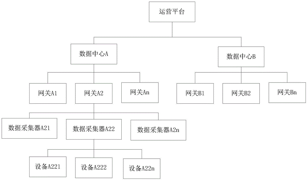
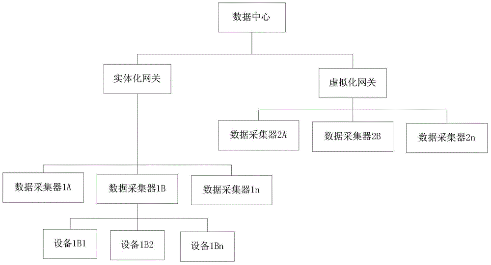
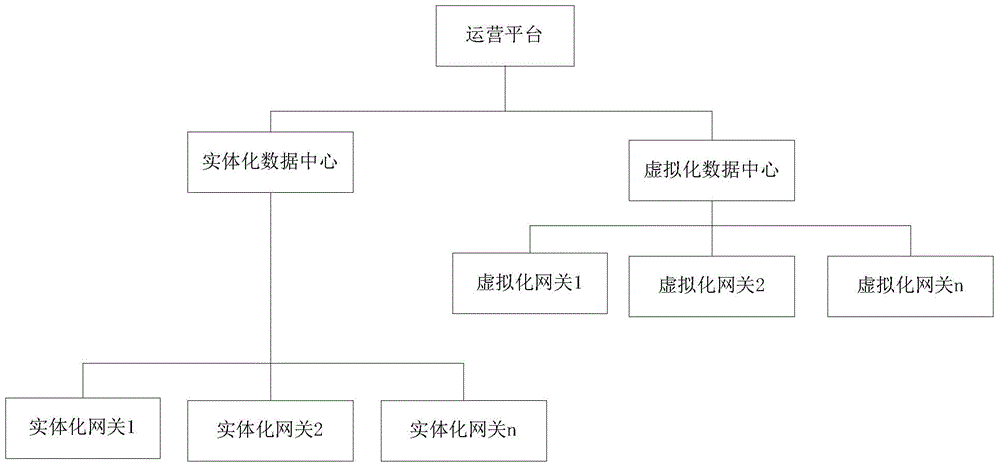
[0036] Such as figure 1 As shown, the multi-level system architecture disclosed by the present invention for a large number of independent device flow data adopts a 4-level architecture, the first level is an operation platform, and the operation platform is connected to multiple data centers at the second level, including data center A and data center B , each data center is connected to multiple gateways, including data center A connected to gateway A1, gateway A2 to gateway An; data center B connected to gateway B1, gateway B2 to gateway Bn; each gateway connected to multiple data collectors, such as gateway A2 Connect data collector A21, data collector A22 to data collector A2n; each data collector is connected to corresponding equipment, for example: data col...


PUM


Abstract

The invention discloses multi-level system architecture for a massive independent equipment data flow. The architecture comprises a data collector, a gateway, a data center and an operating platform, wherein the data collector is connected with the gateway which is connected with the data center, the data center is connected with the operating platform, and the operating platform has a cloud computing function. The architecture disclosed by the invention realizes an industrial large data platform based on a PaaS mode and uses Hadoop as a basic architecture. Moreover, in order to support equipment in various shapes, the system architecture based on the collector-gateway-data center-operating platform is designed, so that changes of user demand can be extremely satisfied.

Description

technical field [0001] The invention relates to a device field solution, in particular to a multi-level system architecture for a large number of independent device flow data. Background technique [0002] Modern enterprises have a large number of production equipment. For the centralized management, monitoring and maintenance of equipment, it is necessary to collect, store and process a large amount of equipment data, which is called stream data. Stream data comes from the control system of the equipment, sensors, and generates data based on time series analog and switch values. In this field, the existing technical framework is an industrial real-time database and a customized data collector, which is used to collect field data and support industrial application software. At present, with the development of big data technology and cloud computing technology, the collection and application of equipment flow data is developing from traditional on-site applications to Intern...

Claims


Application Information

Patent Timeline
Patent Type & Authority Applications(China)
IPC IPC(8): H04L29/08
CPCH04L67/10G06F16/2471
Inventor 李祥
Owner TONGFANG SHENZHEN CLOUD COMPUTING TECH
Learn More