
Channel-by-channel artifact reduction in parallel MRI

A channel, multi-channel technology, applied in the field of medical imaging, can solve problems such as low-noise signal ratio, and achieve the effect of high signal-to-noise ratio

Inactive Publication Date: 2017-12-29
KONINKLJIJKE PHILIPS NV
View PDF3 Cites 0 Cited by
  • Summary
  • Abstract
  • Description
  • Claims
  • Application Information

AI Technical Summary

Problems solved by technology

Spikes can occur due to problems in the coil hardware or unknown sources, but undetected spikes can lead to artifacts present in the reconstructed image
Undetected artifacts lead to lower noise-to-signal ratio in MR data used to reconstruct images

Method used


Image

  • Channel-by-channel artifact reduction in parallel MRI
  • Channel-by-channel artifact reduction in parallel MRI
  • Channel-by-channel artifact reduction in parallel MRI

Examples


Embodiment Construction

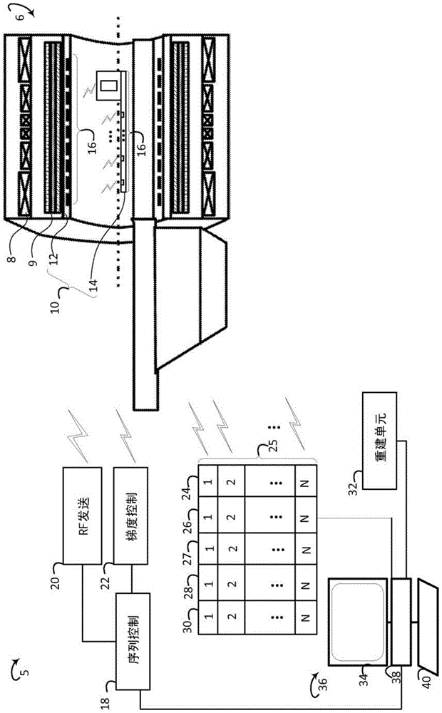
[0025] refer to figure 1 , schematically illustrates an embodiment of the channel-by-channel artifact reduction system 5 . In multi-coil imaging, each of the coils has a different sensitivity to motion and other artifacts. System 5 includes a multi-channel source of MR data, such as a magnetic resonance scanner 6 . The scanner comprises a main magnet 8 which generates a static magnetic field. The scanner comprises one or more gradient coils 9 which apply a gradient magnetic field across the static magnetic field. The scanner 6 includes a multi-channel coil 16 , such as a whole-body coil 12 and / or a multi-channel local coil 14 . Examples of multi-channel local coils include 16-channel cervical coils, 32-channel cardiac coils, and the like. The scanner excites magnetic resonance in the subject, for example using a whole body coil. Sequence controller 18 controls radio frequency (RF) controller 20 and gradient controller 22 . The RF controller 20 controls the application of...


PUM


Abstract

An imaging system (5) includes a plurality of coil channel receivers (26) and one or more processors or modules (38), the plurality of coil channel receivers (26) demodulating signals from multi-channel coils (10) Magnetic resonance data for magnetic resonance data, the multi-channel coil (10) includes a plurality of coil elements (16) spaced apart, each element transmits magnetic resonance data on a corresponding channel (25), the one or more processors or modules (38) configured to detect (26) artifacts in said magnetic resonance data on each channel individually. The one or more processors or modules (38) are further configured to select (27) the magnetic resonance data from channels containing detected artifacts at or below a threshold artifact level , and reconstructing (32) one or more images using the selected magnetic resonance data.

Description

technical field [0001] The following generally relates to medical imaging. The following is particularly applicable in connection with magnetic resonance imaging and image artifact correction and will be described with particular reference thereto. However, it should be understood that the following also applies to other use cases and is not necessarily limited to the aforementioned applications. Background technique [0002] In a magnetic resonance imaging sequence, magnetic resonance is excited in the tissue of a subject. Coils, whole body coils and / or local coils such as cardiac coils, spinal coils, etc., receive weak radio frequency (RF) signals when the excited magnetic resonance decays. The weak RF signal induces a current in the coil, which forms the magnetic resonance imaging data. A whole body coil and / or a local coil is arranged around a surface of a subject and can comprise a plurality of coil elements. The coil elements are distributed around the coil and pos...

Claims


Application Information

Patent Timeline
Patent Type & Authority Patents(China)
IPC IPC(8): G01R33/561G01R33/565
CPCG01R33/565G01R33/283G01R33/385G01R33/543G01R33/5611G01R33/56509
Inventor F·黄W·林
Owner KONINKLJIJKE PHILIPS NV
Learn More