Copper wire drawing die and lubricating system thereof

A technology of wire drawing die and copper wire, applied in the direction of wire drawing die, etc., can solve problems such as poor lubrication effect, achieve the effect of improving wire drawing quality and efficiency, good lubrication effect, and improving lubrication effect

Inactive Publication Date: 2015-04-29
山东中佳电子科技有限公司
View PDF7 Cites 6 Cited by
  • Summary
  • Abstract
  • Description
  • Claims
  • Application Information

AI Technical Summary

Problems solved by technology

The wire passes through the working area and then enters the sizing area. It bears greater extrusion friction in the working area. However, due to the tight action between the wire and the mold...

Method used


Image

  • Copper wire drawing die and lubricating system thereof
  • Copper wire drawing die and lubricating system thereof
  • Copper wire drawing die and lubricating system thereof

Examples


Embodiment 1

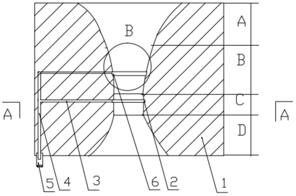
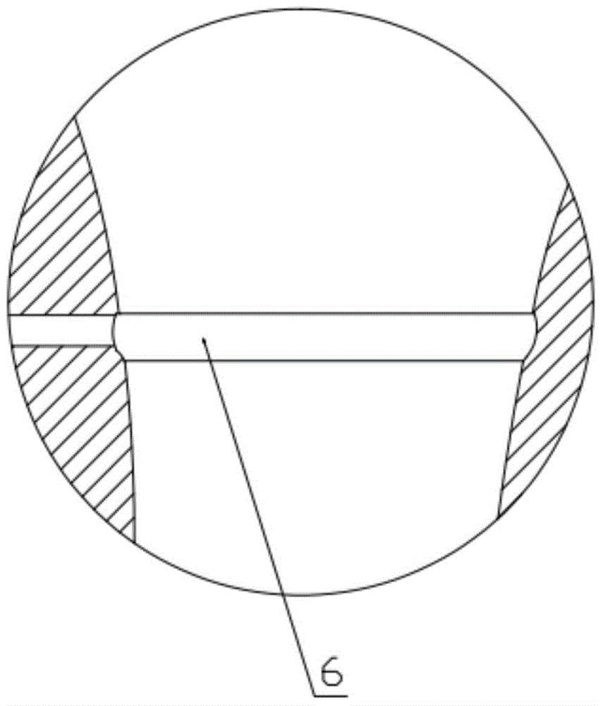
[0026] Such as Figure 1 to Figure 3 As shown, a copper wire drawing die includes a wire die body 1, and the wire die body 1 includes a wire passing hole, and the wire passing hole includes an inlet lubricating area A, a working area B, and a sizing area sequentially from the entrance to the exit. C and the outlet area D, a first annular groove 6 is provided on the inner wall of the working area B, and a flow channel communicating with the outside is provided on the first annular groove 6, and a hydraulic joint is provided at the outer end of the flow channel 5. The groove wall of the first annular groove 6 has a circular arc transition with the inner wall of the working area.

[0027] The fixed area diameter is provided with a second annular groove 2, and the second annular groove 2 communicates with the flow channel.

[0028] The depths of the first and second annular grooves are both 0.1-0.5 mm. The width of the annular groove is 1 to 5 mm

Embodiment 2

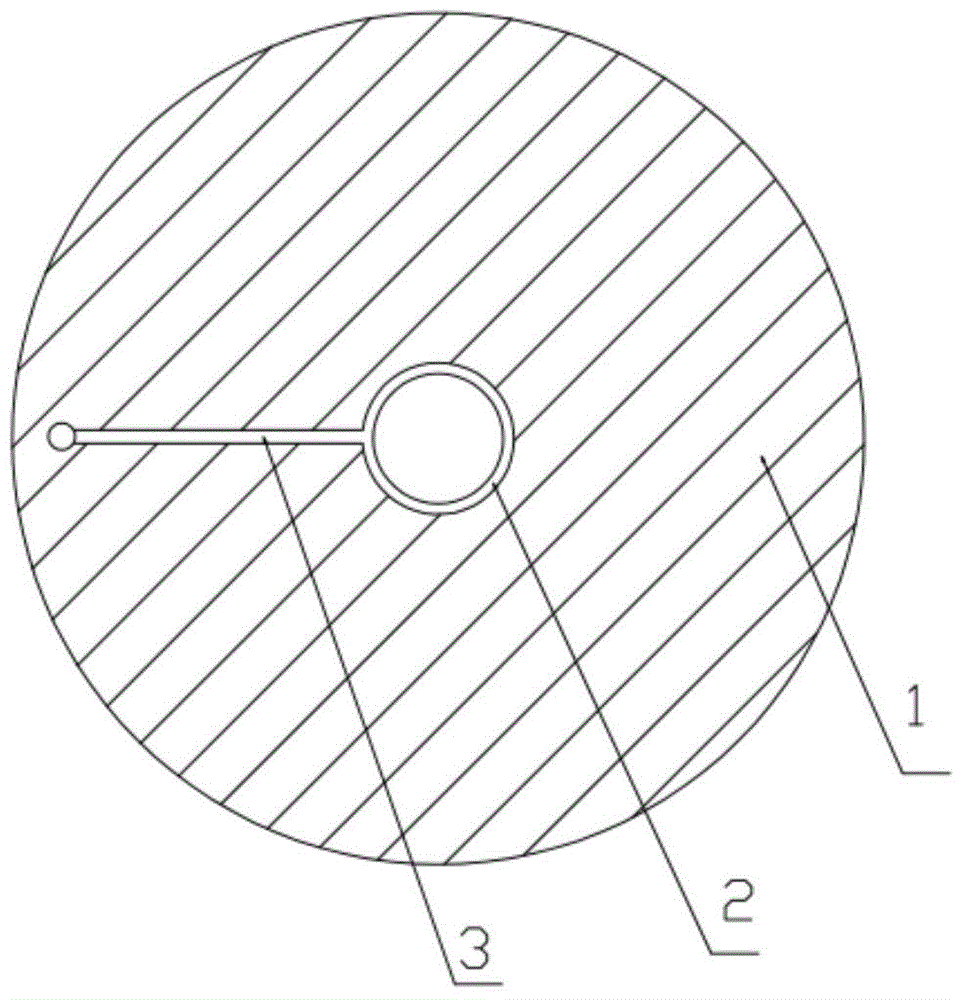
[0030] Such as Figure 4 and Figure 5 As shown, the wire mold body also includes an outer ring body 7, the flow channel includes a radial flow channel 3 and an axial flow channel 4, and the outlet of the axial flow channel 4 is provided with the hydraulic joint 5. With the structure of the outer ring body, the flow channel can be directly processed on the inner ring, and then the outer ring body can be fitted on the inner ring to facilitate the processing of the flow channel.

[0031] The rest of the structure of Embodiment 2 is the same as that of Embodiment 1, and will not be repeated here.

[0032] In specific use, the pressure applied to the annular groove is 0.1-10 MPa, which can better improve the lubrication effect. And should apply pressure while pulling.

[0033] Preferably, the pressure applied to the annular groove is 1-6 MPa.

[0034] Such as Figure 6 As shown, the present invention also provides a copper wire drawing die lubrication system, including the co...


PUM

PropertyMeasurementUnit
Depthaaaaaaaaaa
Widthaaaaaaaaaa

Abstract

The invention relates to a copper wire drawing die. The copper wire drawing die comprises a wire die body, wherein the wire die body comprises a wire passing hole, and the wire passing hole sequentially comprises an inlet lubricating area, a working area, a sizing area and an outlet area from an inlet to an outlet. The copper wire drawing die is characterized in that a first annular groove is formed in the inner wall of the working area, a runner communicated with the outside is formed in the first annular groove, a hydraulic joint is arranged at the outer end of the runner, and the wall of the first annular groove is in circular arc transition with the inner wall of the working area; a second annular groove is formed in the sizing area and communicated with the runner; the runner comprises a radial runner body and an axial runner body, and the hydraulic joint is arranged at an outlet of the axial runner body. The invention further relates to a lubricating system of the copper wire drawing die. The lubricating system comprises the copper wire drawing die and a high-pressure lubricating oil supply device. The copper wire drawing die and the lubricating system have the benefit as follows: drawn copper wires are better lubricated.

Description

technical field [0001] The invention relates to the technical field of wire rod production, in particular to a copper wire drawing die and a lubrication system thereof. Background technique [0002] Wire is widely used in communication, construction, electric power and other departments. Drawing is the most commonly used processing method in wire rod production. The wire drawing die is a very important consumable die in the drawing production of various metal wires, which is closely related to the quality and efficiency of wire drawing. Maintaining good lubrication during the wire drawing process is an important factor to ensure the wire drawing effect. The main working area of ​​the wire drawing die is the inner hole, that is, the wire hole. According to the nature of the work, the inner hole structure can be divided into five sections: entrance area, lubrication area, working area, sizing area, and exit area, and follows the "smooth transition" theory, that is, the junc...

Claims


Application Information

Patent Timeline
IPC IPC(8): B21C3/14
CPCB21C3/02B21C9/00
Inventor 李家亭朱敏
Owner 山东中佳电子科技有限公司
Why Eureka
Try Eureka