
Ornament punching device

A technology for stamping devices and accessories, used in metal processing equipment, forming tools, manufacturing tools, etc., can solve the problems of high noise, difficult mold replacement, slow processing speed of punching machines, etc., so as to reduce noise and energy loss and achieve mechanical mass production. the effect of improving production efficiency

Inactive Publication Date: 2015-04-29
BEIJING TONGHUI JEWELRY
View PDF7 Cites 0 Cited by
  • Summary
  • Abstract
  • Description
  • Claims
  • Application Information

AI Technical Summary

Problems solved by technology

The commonly used stamping equipment is a punch, but the processing speed of the punch is slow, the noise is large, the energy consumption is high, the mold is not easy to replace, it is easy to cause vibration and looseness, and it is also prone to safety accidents.

Method used


Image

  • Ornament punching device
  • Ornament punching device

Examples


Embodiment

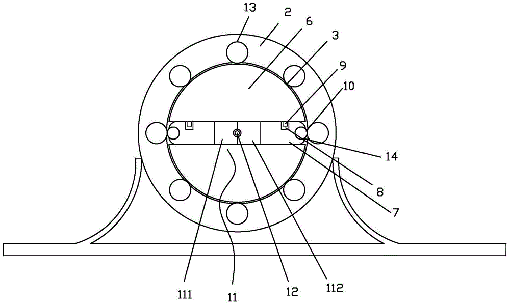
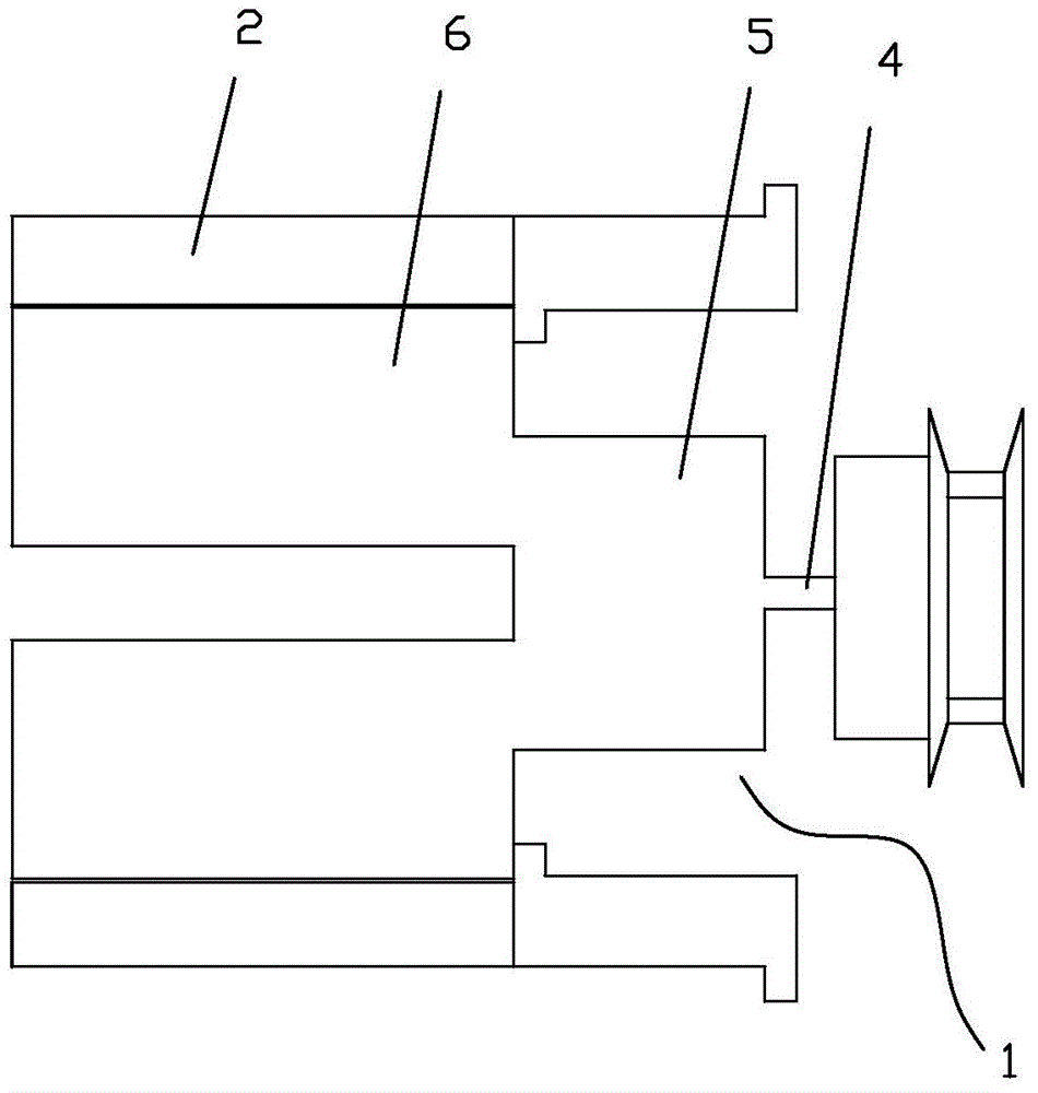
[0018] Such as figure 1 with figure 2 A jewelry stamping device shown includes a driving wheel 1 and a driven wheel 2, the driving wheel 1 is located inside the driven wheel 2, and the driven wheel 2 is fixed on the base. The inner wall of the driven wheel 2 is provided with a cylindrical cavity with a notch, and a first cylinder 13 is inserted in the cylindrical cavity with a notch, and a part of the first cylinder 13 protrudes from the notch to form a thimble 3, and the thimble 3 Correspondence in pairs. The driving wheel 1 includes a drive shaft 4 , a transmission shaft 5 and a rotating shaft 6 . A hammer 7 is arranged in the rotating shaft 6, and the hammer 7 is provided with a groove 8, and the width of the groove 8 is 5mm. The width is 3 mm, and the top of the hammer 7 is provided with a cylindrical cavity with an opening, and the cylindrical cavity with an opening is inserted into a second cylinder 14 , and a part of the second cylinder 14 protrudes from the opening...


PUM


Abstract

The invention discloses an ornament punching device. The ornament punching device comprises a driving wheel and a driven wheel; the driving wheel is positioned in the driven wheel, and the driven wheel is fixed on a seat; convex ejector pins which are pairwise correspondingly arranged are mounted on the inner sidewall of the driven wheel; the driving wheel comprises a driving shaft, a transmission shaft and a rotating shaft; a punching hammer equipped with a concave groove is arranged in the rotating shaft; a convex strip corresponding to the concave groove is arranged on the rotating shaft, wherein the concave groove is wider than the convex strip; a convex striker is arranged at the outer part of the punching hammer; a forming die is arranged in the punching hammer, wherein the forming die is of a split type structure and comprises a left side and a right side; a cavity is formed in the part in which the left die and the right die are butted; the cavity combination is a cavity when the left die and the right die are butted. With the adoption of the ornament punching device, the production efficiency can be greatly increased; the noise and energy loss in production can be reduced; the die can be conveniently replaced; the defects that workers are easily injured by crashing a punching tool and the safety accident is easily caused can be overcome.

Description

technical field [0001] The invention relates to an ornament processing machine, in particular to an ornament stamping device. Background technique [0002] The commonly used manufacturing methods of jewelry are pouring method and stamping method. Since the casting method needs to make a mold every time, the process is complex, the process is cumbersome, the production speed is slow, and the energy consumption is large. Therefore, people prefer to use the stamping method to make jewelry. In addition, various industrial parts are also commonly used. Stamping method. The commonly used punching equipment is a punching machine, but the processing speed of the punching machine is slow, the noise is large, the energy consumption is high, the mold is not easy to replace, it is easy to cause vibration and looseness, and it is also prone to safety accidents. Contents of the invention [0003] In order to improve the processing speed and safety, the invention provides an ornamen...

Claims


Application Information

Patent Timeline
Patent Type & Authority Applications(China)
IPC IPC(8): B21D37/10
CPCB21D37/10
Inventor 苗世祥安家鹏刘爱良
Owner BEIJING TONGHUI JEWELRY
Learn More