All-hydraulic die forging hammer

A die forging hammer, full hydraulic technology, applied in the direction of forging/pressing/hammer device, forging press, forging press, etc., can solve the problem of difficult precision die forging, increasing the gap between the slider and the bed, affecting the working accuracy of the whole machine, issues of reliability and security

Inactive Publication Date: 2015-04-29
CHANGZHOU JINGLING CASTING & FORGING
View PDF0 Cites 2 Cited by
  • Summary
  • Abstract
  • Description
  • Claims
  • Application Information

AI Technical Summary

Problems solved by technology

It overcomes the shortcomings of the split bed that affects the working accuracy, reliability and safety of the whole machine due to the rigidity of the connection
However, there is no corresponding guide rail structure on the above-mentioned slider, and there is a defect of temperature compensation. In order t

Method used


Image

  • All-hydraulic die forging hammer
  • All-hydraulic die forging hammer

Examples


Embodiment Construction

[0015] The present invention will be further described below in conjunction with the accompanying drawings.

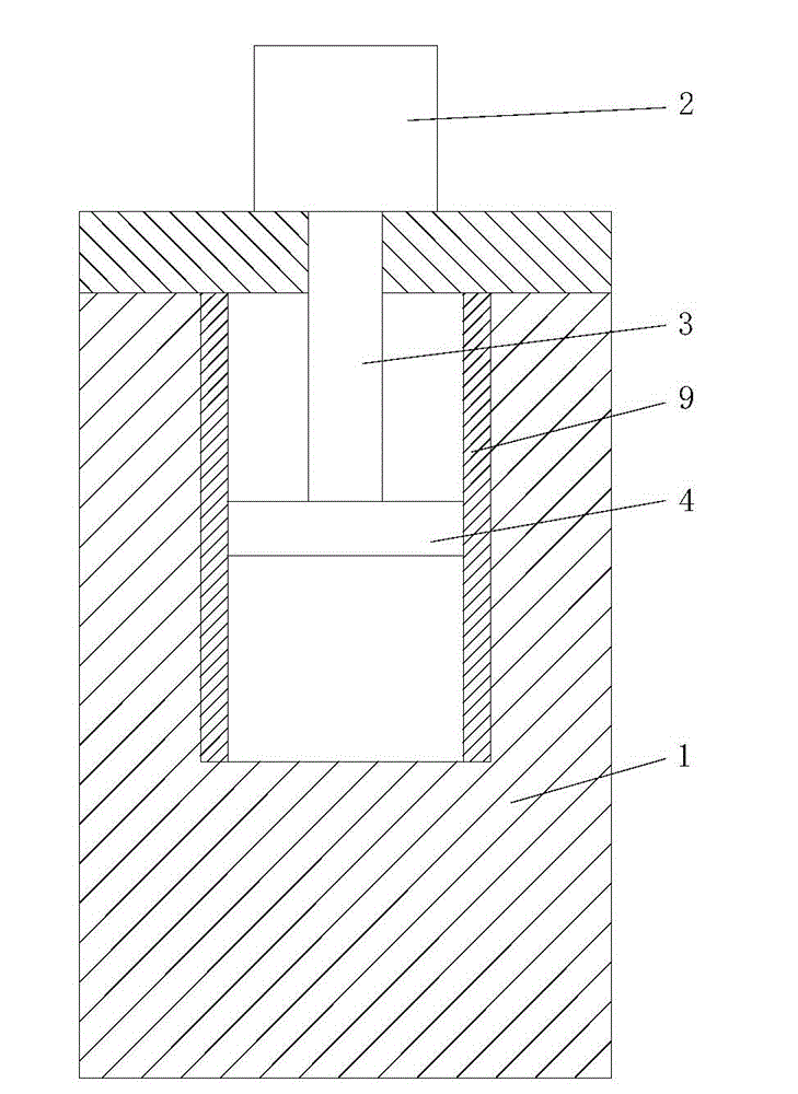
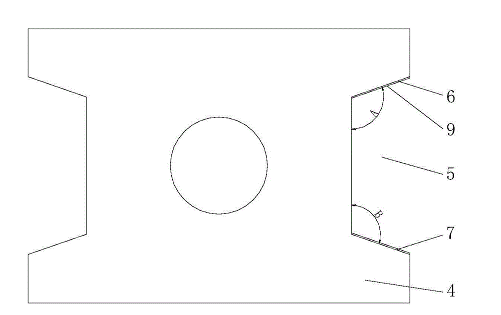
[0016] refer to figure 1 and figure 2 , the full hydraulic die forging hammer of the present invention includes a U-shaped bed 1, a full hydraulic power head is arranged on the U-shaped bed, the full hydraulic power head includes a working cylinder 2, a hammer rod 3 is housed in the working cylinder 2, and the hammer The lower end of the rod is connected to the slider 4, and the first side and the second side of the slider 4 in contact with the bed are respectively provided with guide grooves 5, and each guide groove has a groove bottom and a first guide surface located at the bottom of the groove 6 and the second guide surface 7, wherein the first guide surface 6 and the second guide surface 7 are inclined surfaces, the angle A formed between the first guide surface and the bottom surface of the groove is 120-135 degrees, and the angle A is preferably is 120 degree...


PUM


Abstract

The invention relates to an all-hydraulic die forging hammer which comprises a U-shaped lathe bed, wherein the U-shaped lathe bed is provided with an all-hydraulic power head; the all-hydraulic power head comprises a working cylinder; a hammer lever is mounted in the working cylinder; the lower end of the hammer lever is connected with a sliding block; guide grooves are respectively formed in the first side surface and the second side surface, which are contacted with the lathe bed, of the sliding block; each guide groove is internally provided with a groove bottom surface, as well as a first guide surface and a second guide surface arranged on the groove bottom surface, wherein both the first guide surface and the second guide surface are inclined planes; guide rails are arranged on the opposite inner side wall surfaces of the U-shaped lathe bed respectively, and are inserted into the guide grooves to be in sliding fit with the guide grooves. The all-hydraulic die forging hammer has the advantage of high guide precision, and the die forging precision is not affected by a temperature rise.

Description

technical field [0001] The invention relates to a full hydraulic die forging hammer. Background technique [0002] A full hydraulic die forging hammer is disclosed in the prior art, which includes a U-shaped integral bed, on which there is a full hydraulic power head, and the full hydraulic power head has a working cylinder, the working cylinder is covered with an outer cylinder, and the working cylinder is connected to work There is an annular hydraulic oil channel between the working cylinder and the outer cylinder. The upper end of the annular hydraulic oil channel is connected to the pressure oil port, and the lower end is connected to the rod chamber of the working cylinder. The working cylinder and the outer cylinder are connected to the oil tank through the integrated block. The fuel tank is set outside the outer cylinder and fixed on the upper end of the outer cylinder through the integrated block. The working parts connected to the working cylinder include: a hamme...

Claims


Application Information

Patent Timeline
IPC IPC(8): B21J9/02B21J9/12
Inventor 余锦吴光辉史文亮
Owner CHANGZHOU JINGLING CASTING & FORGING
Why Eureka
Try Eureka