High-strength high-rigidity guide upright column

A high-rigidity, high-strength technology, applied in the direction of manufacturing tools, forging/pressing/hammer devices, forging/pressing/hammering machinery, etc., can solve the problem of poor bending resistance and anti-eccentric load resistance, large consumables, low strength and rigidity and other problems, to achieve the effect of increased anti-eccentric load capacity and increased flexural section modulus

Inactive Publication Date: 2015-04-29
史晨
View PDF0 Cites 0 Cited by
  • Summary
  • Abstract
  • Description
  • Claims
  • Application Information

AI Technical Summary

Problems solved by technology

[0003] The existing high-strength guide column is composed of three parts: the upper solid cylinder section, the lower solid cylinder section and the middle cylinder section. The t

Method used


Image

  • High-strength high-rigidity guide upright column

Examples


Embodiment Construction

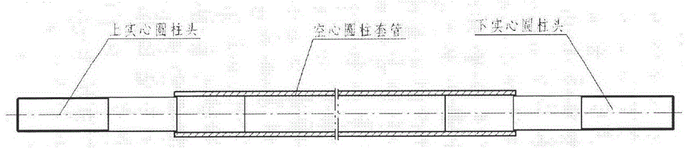
[0010] The high-strength and high-rigidity guiding column of the present invention includes an upper solid cylindrical section, a lower solid cylindrical section and a hollow cylindrical sleeve, and the upper solid cylindrical section, the lower solid cylindrical section and the hollow cylindrical sleeve are located on the same line On the axis, the upper part of the upper solid cylindrical section is the working section, the lower part of the lower solid cylindrical section is the working section, and the lower part of the upper solid cylindrical section is inserted into the upper end of the hollow cylindrical sleeve from top to bottom, and between the two Interference fit: the upper part of the lower solid cylindrical section is inserted into the lower end of the hollow cylindrical sleeve from bottom to top, and the two are interference fit.

[0011] The depth to which the upper solid cylindrical section and the lower solid cylindrical section are respectively inserted into t...


PUM


Abstract

The invention provides a high-strength high-rigidity guide upright column, and belongs to the technical field of machine tools. The high-strength high-rigidity guide upright column comprises an upper solid column section, a lower solid column section and a hollow column casing, wherein the upper solid column section, the lower solid column section and the hollow column casing are positioned on one same axis; the upper part of the upper solid column section is a working section; the lower part of the lower solid column section is also a working section; the lower part of the upper solid column section is inserted into the upper end of the hollow column casing from top to bottom; the upper solid column section and the hollow column casing are in interference fit; the upper part of the lower solid column section is inserted into the lower end of the hollow column casing from bottom to top; the lower solid column section and the hollow column casing are in interference fit; the depth that the upper solid column section and the lower solid column section are respectively inserted into the hollow column casing is 3-5 times of the respective diameters of the upper solid column section and the lower solid column section. According to the mechanical bending strength theory, the bending-resistant section modulus of a hollow column rod with equal cross sections is greater than that of a solid column rod with equal cross sections, that is when the identical bending-resistant section modulus requirement is met, the weight of the hollow column rod needs to be less than that of the solid column rod; particularly, in a wide table surface hydraulic machine, the bending-resistant cross section modulus of the upright column adopting a hollow column casing structure is increased when being compared with that of a solid upright column with equal mass, the unbalance loading prevention capacity of the upright column is also increased, and the product verification results show that the unbalance loading prevention capacity of the upright column is 2-4 times of that of an ordinary solid upright column.

Description

technical field [0001] The invention relates to a vertical machine tool, in particular to a high-strength and high-rigidity guiding column, which belongs to the technical field of machine tools. Background technique [0002] The high-strength guide column is mainly used in the wide-table four-column hydraulic press of large-scale forging equipment to provide guidance for the reciprocating motion of the slider of the hydraulic press, greatly improve the anti-eccentric load capacity of the fuselage, and avoid the wear of the guide surface, thereby ensuring the pressing and forming accuracy of the parts and the stability of the mold. service life. [0003] The existing high-strength guide column is composed of three parts: the upper solid cylinder section, the lower solid cylinder section and the middle cylinder section. The three sections are all solid structures, heavy in weight, large in consumables, relatively low in strength and stiffness, and resistant to bending and defl...

Claims


Application Information

Patent Timeline
IPC IPC(8): B21J13/04
CPCB21J13/04
Inventor 史晨
Owner 史晨
Why Eureka
Try Eureka