Automatic quick centring clamping mechanism dedicated for axle type or cover type part

A clamping mechanism and sleeve technology, applied in clamping devices, metal processing machine parts, clamping and other directions, can solve the problems of increasing cost, affecting efficiency, and slow clamping speed.

Inactive Publication Date: 2015-04-29
ANHUI WHITE RABBIT POWER
View PDF5 Cites 23 Cited by
  • Summary
  • Abstract
  • Description
  • Claims
  • Application Information

AI Technical Summary

Problems solved by technology

[0002] In the automatic production line or flexible machine tools of shaft or sleeve parts, the automatic centering clamping of the workpiece is currently generally using a three-jaw centering chuck, which includes manual clamping, hydraulic clamping and pneumatic clamping. method, there are shortcomings such as slow clamping speed and clamping range. When changing different

Method used


Image

  • Automatic quick centring clamping mechanism dedicated for axle type or cover type part
  • Automatic quick centring clamping mechanism dedicated for axle type or cover type part

Examples


Embodiment Construction

[0008] The present invention will be further described below in conjunction with the accompanying drawings.

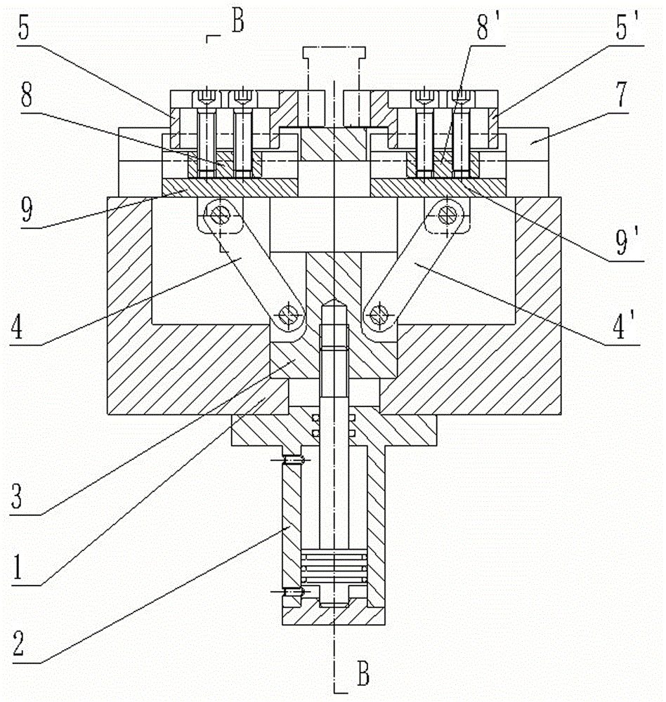
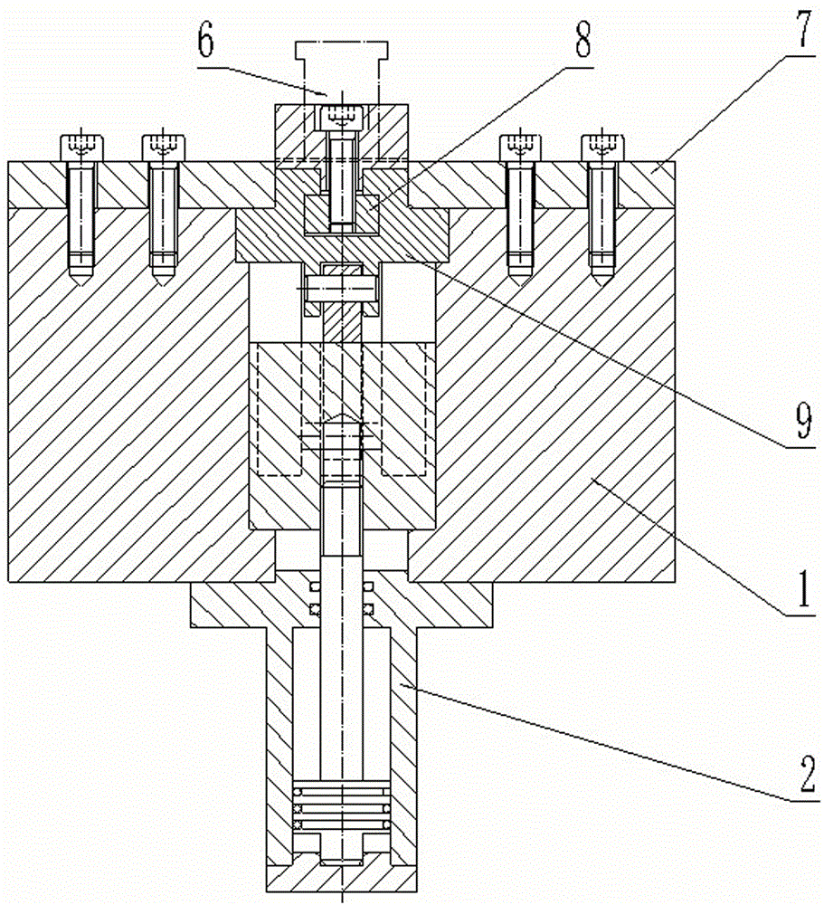
[0009] Such as figure 1 , figure 2 It can be seen that the special automatic fast centering clamping mechanism for shaft or sleeve parts of the present invention includes a seat body 1 with a U-shaped cross section, a cylinder 2 is arranged under the seat body 1, and the movement in the chute on the lower end surface of the seat body 1 The sliding connecting rod shaft 3 is provided, and the cylinder 2 is connected with the sliding connecting rod shaft 3 through the piston rod; two sliding blocks 9, 9' are symmetrically arranged in the upper slideway of the seat body 1, and the two sliding blocks 9, 9' A pressure plate 7 is arranged on the seat body 1 above, and two connecting rods 4, 4' are symmetrically arranged in the inner cavity of the seat body 1. The rod shaft 3 is connected, and the other end is respectively connected with the two sliders 9, 9' through the pi...


PUM


Abstract

The invention provides an automatic quick centring clamping mechanism dedicated for an axle type or cover type part. The automatic quick centring clamping mechanism can carry out automatic centring clamping on the axle type or cover type part and has the advantages of high clamping speed and wide positioning range. The automatic quick centring clamping mechanism comprises a seat body of which the section is of a U shape; a cylinder is arranged below the base; a sliding connecting rod shaft is movably arranged in a chute in the lower end surface of the seat body; the cylinder is connected with the sliding connecting rod shaft via a piston rod; two sliding blocks are symmetrically arranged on the left and the right in an upper slideway of the seat body; the seat body above the two sliding blocks is provided with a platen; two connecting rods are symmetrically arranged in the inner cavity of the seat body; one end of each connecting rod is connected with the sliding connecting rod shaft via a hinge pin; the other ends of the connecting rod are respectively connected with two sliding blocks via hinge pins; the two sliding blocks are respectively movably provided with two centring elements via T-shaped grooves; the two centring elements are respectively fixedly arranged on two sliding blocks via two locking blocks and locking bolts.

Description

technical field [0001] The invention relates to a mechanical processing device, in particular to an automatic fast centering clamping mechanism for shaft or sleeve parts. Background technique [0002] In the automatic production line or flexible machine tools of shaft or sleeve parts, the automatic centering clamping of the workpiece is currently generally using a three-jaw centering chuck, which includes manual clamping, hydraulic clamping and pneumatic clamping. The method has the disadvantages of slow clamping speed and clamping range. When changing different varieties, it is often necessary to adjust and process the clamping jaws, which affects efficiency and increases costs. Especially in the processing and positioning of the cylinder liner, the general manufacturer adopts the positioning plate method, and the positioning plate is replaced when the product is changed, which has a more prominent impact on work efficiency and cost. Therefore, it is necessary to design a ...

Claims


Application Information

Patent Timeline
IPC IPC(8): B23B31/30B23B31/16
CPCB23Q3/00B23Q2703/04B23Q2703/10
Inventor 汪舵海张志强
Owner ANHUI WHITE RABBIT POWER
Why Eureka
Try Eureka