Telecommunication and position detection device of overhead and gantry crane
A detection device and remote communication technology, applied in the field of remote communication and position detection devices, can solve the problems of difficulty in laying and retracting, the bandwidth and reliability cannot meet the clear and stable transmission of video signals of cameras on cranes, etc., and can solve the problem of bandwidth limitation and stability problems, increase flexibility, and solve the effect of retractable problems
- Summary
- Abstract
- Description
- Claims
- Application Information
AI Technical Summary
Problems solved by technology
Method used
Image
Examples
Embodiment 1
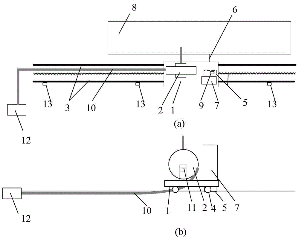
[0023] Such as figure 1 (a) Shown in (b), the present invention comprises trolley 1, optical cable reel 2, trolley running track 3, trolley meshing transmission device 5, trolley connecting device 6 and trolley control device 7.
[0024] A detachable connection device 6 is connected between the trolley 1 and the crane 8. When the crane needs remote communication and control, the trolley connection device is connected and fixed with the crane. When the crane is running, the connection device drives the trolley to run together; When the crane does not need remote communication and control, the connecting device is separated from the crane, and the trolley 1 can be driven by the driver on the car and travel through the meshing transmission device.
[0025] The meshing transmission device 5 is installed on the trolley 1, and a multi-turn absolute value encoder 9 is installed on the meshing transmission device. When the crane cart moves, it drives the trolley to move synchronously...
Embodiment 2
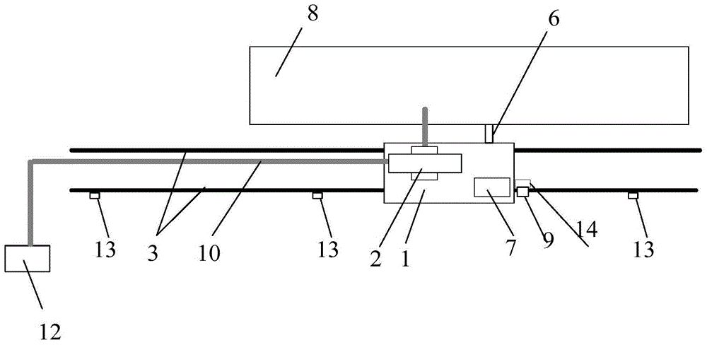
[0029] Such as figure 2 As shown, the present invention includes a trolley 1, an optical cable reel 2, a trolley running track 3, a trolley position detection device, a trolley connecting device 6 and a trolley control device 7. The difference from Embodiment 1 is that when the crane does not require remote communication and control, the trolley wheels are connected to the drive motor through the reducer, and the trolley is driven by the driver on the vehicle. The motor drives the wheels through the reducer to walk by itself. The trolley position detection device is realized by the free wheel 14 and the multi-turn absolute value encoder 9 installed on the free wheel rolling on the trolley running track. When the crane cart moves, it drives the trolley to move synchronously, and the free wheel drives the absolute value encoder to accurately measure the position of the crane cart.
Embodiment 3
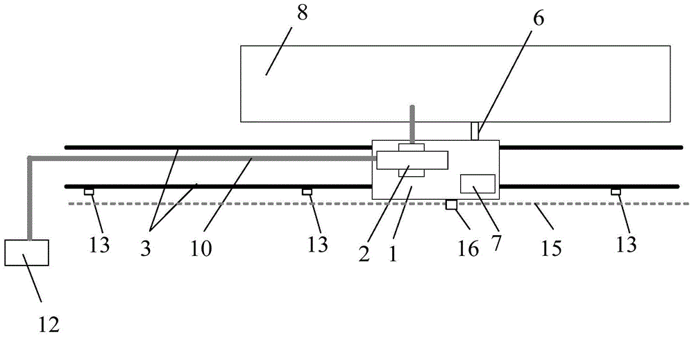
[0031] Such as image 3 As shown, the composition unit of the present invention is the same as the above-mentioned embodiment 2, and the difference is that the position detection device of the trolley consists of laying a position encoding device 15 (such as Gray busbar, position encoding belt, etc.) The signal receiving device 16, the position signal receiving device sends the position signal to the PLC in the power control box.
PUM
 Abstract
Description
Claims
Application Information
 - R&D
- Intellectual Property
- Life Sciences
- Materials
- Tech Scout
- Unparalleled Data Quality
- Higher Quality Content
- 60% Fewer Hallucinations
Browse by: Latest US Patents, China's latest patents, Technical Efficacy Thesaurus, Application Domain, Technology Topic, Popular Technical Reports.
© 2025 PatSnap. All rights reserved.Legal|Privacy policy|Modern Slavery Act Transparency Statement|Sitemap|About US| Contact US: help@patsnap.com


