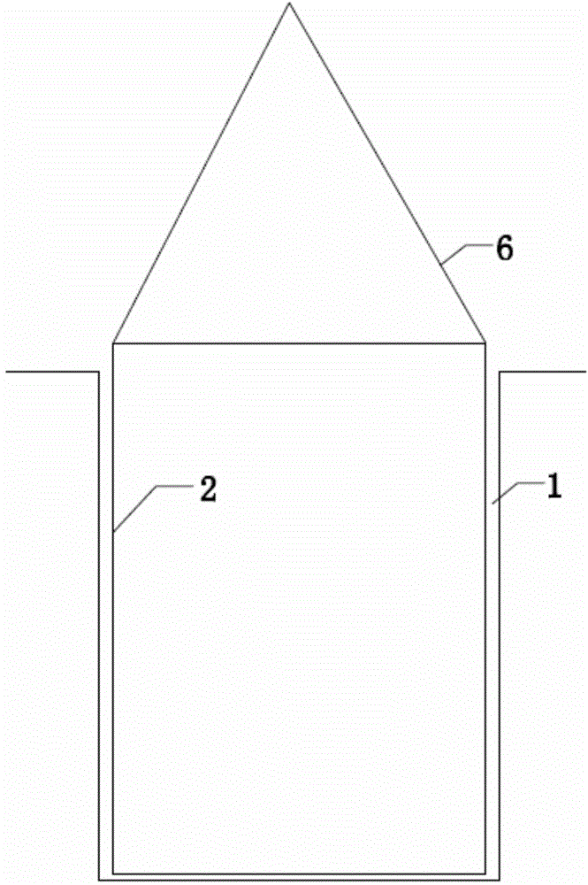
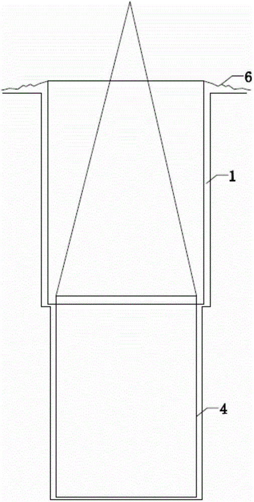
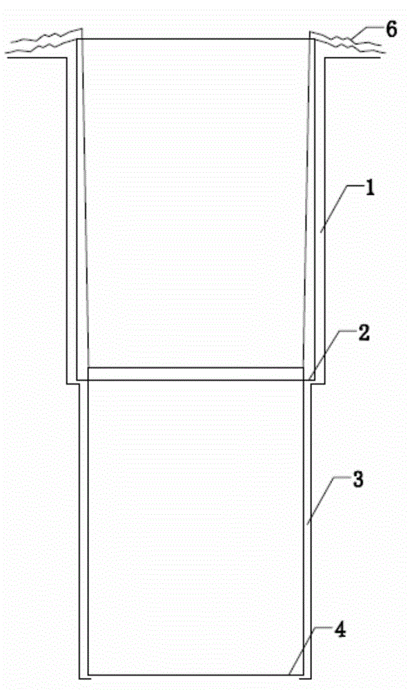
[0031] A method for constructing super-large-diameter all-steel casing dry-worked hole-forming cast-in-place piles, comprising the following steps:
[0032] Step a, measuring and placing the pile position; after measuring and placing the pile position in the present embodiment, the drilling rig is put in place, the drilling rig of the present embodiment is a rotary drilling rig, and a telescopic automatic leveling device is arranged on the chassis of the rotary drilling rig, There are instruments in the operating room to accurately display the electronic readings. When the drill bit is aligned with the cross line at the center of the pile position, all data can be locked without further adjustment. within 2cm.
[0033] In this embodiment, the torque is generated by the fully hydraulic power head of the rotary drilling rig, and the drilling pressure is provided by the hydraulic cylinder installed on the drill frame. These two parts are transmitted to the drill bit through the telescopic drill rod, and the drilled slag is filled into the bottom The drill bucket with flexible baffle is lifted out of the hole by the main winch.
[0034] Step b, embedding orifice steel casing 2: if figure 1 As shown, first dig out the first pile hole 1 at the pile site, then hoist the hole steel casing 2 into the first pile hole 1, adjust the position of the hole steel casing 2 until it is in line with the first pile hole 1 concentric, the diameter of the hole steel casing 2 is smaller than the inner diameter of the first pile hole 1, the bottom of the first pile hole 1 is filled with a layer of clay, and the hole steel casing 2 and the first pile hole 1 The gap between them is filled with clay, and the lower end surface of the hole steel casing 2 is set at the bottom of the first pile hole 1. In this embodiment, the depth of the first pile hole 1 is 5m, and the hole steel casing The thickness of 2 is greater than or equal to 20mm. After installing the orifice steel casing 2, it has the functions of guiding the drilling tool, controlling the pile position, isolating ground water leakage, preventing the orifice from collapsing, raising the static pressure head in the hole and fixing the steel cage, etc. effect.
[0035]In the present embodiment, the specific steps of step b are as follows: first, bury the control pile on the orthogonal cross line passing through the center point 80-100 cm outside the steel casing 2 of the opening to be installed, and then dig out the specific hole outside the pile position The mouth steel casing 2 is 60cm larger than the first section of the pile hole 1, and its depth is 0.2m. Fill the 20cm thick clay at the bottom of the pit and compact it, and then the hole steel casing 2 is hoisted into the hole with a wire rope 6; In the process of hoisting, first find out the center of circle of the hole steel casing 2. In this embodiment, find out the center of circle by pulling orthogonal cross lines, and then find out the center of the pile position by controlling the method of pile stakeout, and move The hole steel casing 2, make the center of the hole steel casing 2 coincide with the center of the pile position, and at the same time use a level ruler (or pendant) to verify the verticality of the casing, the top height of the hole steel casing 2 at this time 0.3m above the ground, and then backfill clay with suitable water content around the orifice steel casing 2, and compact it layer by layer. When tamping, the deflection of the orifice steel casing 2 should be prevented. After the orifice steel casing 2 is buried, Recheck the center deviation of the hole steel casing 2, and when the center deviation is within the preset range, the drilling rig can be moved in place and drilled.
[0036] In this embodiment, after step b, the first section of the pile hole 1 is drained. The drainage method is: a drainage ditch is arranged around the foundation pit of the pile position, and the distance between the drainage ditch and the foundation pit of the pile position is 30m to 40m, and then set up a water collection well at the location of the post-pouring belt leading out of the foundation pit, so that the groundwater seeping out of the foundation pit (the water in the first pile hole 1) and rainwater will gather in the water collection well through the drainage ditch, and then pumped Its discharge, in the present embodiment, before step c, artificial precipitation is carried out to the area near the pile hole 3 of the second section with the tube well dewatering method, and 19 precipitation wells are arranged outside the pile hole 3 of the second section, and the wells of the precipitation wells The distance is 17m~18m, the depth of the dewatering well is 15m, and the aperture of the dewatering well is 800mm. The dewatering well is drilled with a rotary drilling rig and pumped by a submersible pump. After the dewatering is completed, it is backfilled with sand.
[0037] Step c, excavating the second pile hole 3: as figure 2 As shown, the second section pile hole 3 is dug downward from the first section pile hole 1, the aperture of the second section pile hole 3 is smaller than the outer diameter of the hole steel casing 2, and the bottom of the second section pile hole 3 is located at the foundation the top of the bearing layer of the rock;
[0038] Step d, hoist the inner steel casing 4 into the second pile hole 3, and fill the gap between the second pile hole 3 and the inner steel casing 4 with clay, such as image 3 As shown, the outer diameter of the inner steel casing 4 is smaller than the inner diameter of the second pile hole 3, and the lower end surface of the inner steel casing 4 is supported on the bearing layer of the bedrock; in this step, the depth of the inner steel casing 4 Determined according to the burial depth of the bedrock, the diameter of the inner steel casing 4 is 140mm larger than the pile diameter of the second section pile hole 3, and the thickness of the steel plate of the inner steel casing 4 is not less than 20mm. The inner steel casing 4 of the present embodiment has a guide Positive drilling tools, controlling pile position, isolating groundwater leakage, preventing hole wall from collapsing, raising the static pressure head in the hole and fixing the reinforcement cage, etc., because the inner steel casing 4 is longer, it can be released while drilling, until the inner steel casing 4 is longer. Casing 4 enters bedrock, check hole position at any time.
[0039] Step e, excavate and ream the hole below the pile hole 3 of the second section down to the preset depth, and pour concrete.
[0040] like Figure 4 shown to Image 6 As shown, in step e of this embodiment, when the concrete is poured to the upper part of the second pile hole 3, the inner steel casing 4 is pulled out with a crane, and then the concrete is poured upward; when the concrete is poured to the first pile hole At the top of the hole 1, the hole steel casing 2 is pulled out with a crane, which can effectively improve the quality of concrete pouring.
[0041] In step e of this embodiment, when the preset reaming size at the pile end is equal to the maximum radial size of the reaming bit, when the drilling depth of the soil-borrowing bit of the drilling rig reaches the bearing layer of the bedrock, the The soil-borrowing bit at the end of the rod is replaced with a reaming bit, and then the torsional power of the drill rod is used to rotary dig and cut the soil. The reaming bit expands radially during the cutting process until the straight reaming bit is fully opened. After completing the reaming construction, when the preset reaming size at the pile end is not greater than the maximum outer diameter of the preset reaming bit in the site, the hole is formed by directly drilling and excavating through the reaming bit, which has high construction efficiency and low labor intensity , the beneficial effect of high safety.
[0042] In step e of this embodiment, when the preset reaming size at the pile end is greater than the maximum radial size of the reaming bit, when the drilling depth of the soil-borrowing bit of the drilling rig reaches the bearing layer of the bedrock, the Replace the soil-borrowing bit at the end of the rod with a reaming bit, and use the torsional power of the drill rod to rotary dig and cut the soil. The reaming bit expands radially during the cutting process until the straight reaming bit is fully opened, and then Manual reaming is used to complete the rest of the construction until the hole diameter reaches the preset reaming size at the pile end. The method of "rough excavation" through the reaming bit and supplemented by manual reaming "finishing" overcomes the preset expansion in the construction site. When the hole drill bit is smaller than the preset reaming size of the pile end, the defect that the hole cannot be directly formed, and compared with the purely manual excavation method, it has the beneficial effects of high construction efficiency and low labor intensity, and by setting the hole steel casing 2 And the way of the inner steel casing 4 effectively avoids the collapse of the soil body and improves the construction safety.
[0043] In step e of this embodiment, the method of manual reaming is to ream the holes segment by segment from top to bottom, and complete the reaming from the center to the periphery in each segment.
[0044] The specific gravity of the clay between the hole steel casing 2 and the first section pile hole 1, and the clay between the inner steel casing 4 and the second section pile hole 3 of this embodiment is 1.1 to 1.3, and the viscosity of the clay is 19. ~28 pa.s.
[0045] In step e of this embodiment, before pouring concrete, set a flat-bottomed sand dredging bucket at the end of the drill pipe, and clean up the virtual soil or mud and stone sediment with large particle size at the bottom of the hole. After cleaning, measure the hole depth with a measuring rope until the desired set value.
[0046] In step e of this embodiment, concrete is poured downward from the storage hopper through the conduit 5, and the initial concrete pouring volume v≥(h1+h2)×πD2/4+h3×πd2/4, where v is the quantity required for pouring the first batch of concrete, D is the diameter of the pile hole, h1 is the distance from the bottom of the pile hole to the bottom of the conduit 5, h2—the initial embedding depth of the conduit 5, d is the inner diameter of the conduit 5, and h3 is the concrete in the conduit 5 when the concrete in the pile hole reaches the embedding depth h2 The height difference between the top surface and the top surface of the concrete in the pile after the first pouring.
[0047] h3≡H×W/C in step e of this embodiment, where H is the height from the top surface of the concrete in the pile to the top surface of the pile after the first pot is poured, W is the specific gravity of the mud in the pile hole, and C is the concrete density.
[0048] In this embodiment, after step e, the pile foundations in the first pile hole 1 and the second pile hole 3 are detected, and the detection methods include strain detection, ultrasonic detection, core drilling detection and rock foundation load test.
[0049] The excavation and reaming in this embodiment adopt the drilling operation method of mud retaining wall or the dry operation method of steel casing retaining wall. Slurry, and use the mud pump to send the mud in the mud pool to the pile hole for construction. The specific gravity of the mud in this embodiment is 1.1-1.3, the viscosity is 19-28pa.s, and the relative density of the mud in the pebble layer is controlled at 1.20-1.25. When filling the hole, use the mud pump to pump the mud back to the mud pool for drilling the next pile. The mud pool is connected with a mud pool, a mud purification device and a mud circulation device.
[0050] The specific drilling method of this embodiment is as follows: first put the drilling rig in place, start drilling after the mud is qualified, and press a drilling bucket equipped with a telescopic drill rod into the soil through the torque provided by the turntable, and the bottom door of the drilling bucket is installed. There are oblique bucket teeth for cutting the soil. When drilling, the footage is 60cm each time. During the rotary excavation process of the 5m-8m section of the hole, the verticality is monitored by the control panel and the deviation is corrected in time. Grouting in the hole keeps the water head in the hole at a certain height to increase the pressure and ensure the quality of the retaining wall. When drilling, use the self-weight of the drill to cut the rotating inclined bucket teeth into the soil or set a pressure bar on the upper part of the drilling bucket to cut the inclined bucket teeth into the picture. There is also a flexible baffle at the bottom of the drilling bucket, which can So that the cut soil will not fall back after entering the drilling bucket. After the drilling bucket is filled with soil, stop applying torque, lift the bucket to discard the muck nearby, and shovel it to the designated place with a loader.
[0051] In this embodiment, the hole wall is solid, vertical, and smooth by drilling at a slow speed during spud, so as to prevent the hole from collapsing.
[0052] In the drilling process of this embodiment, according to different geological conditions, four kinds of drill bits can be selected: earth-digging drill bits, sand-digging drill bits, barrel drills, and auger drill bits.
[0053] The drilling earthwork cleaning method after the present embodiment drilling is as follows: Excavator and loader are set on the spot, and the earthwork taken out of drilling into hole is cleared to the side of the field with excavator and loader immediately and transported outside.
[0054] Through the above method, by sequentially excavating two sections of pile holes, combined with the method of rotary drilling rig to form holes, compared with the method of manual hole digging pile construction, it has better safety, high construction efficiency, and low labor intensity, etc. Beneficial effects, and The method of setting the hole steel casing 2 and the inner steel casing 4 on the first pile hole 1 and the second pile hole 3 has the functions of guiding the drilling tool, controlling the pile position, isolating ground water leakage, and preventing the hole The beneficial effects of collapse, raising the static pressure head in the hole and fixing the steel cage, and the hole steel casing 2 and the inner steel casing 4 are supported by the vertical support force below them, (such as the first section of the pile hole 1 It is supported on the top surface of the pile hole 3 in the second section, and the pile hole 3 in the second section is supported on the bedrock bearing layer), which has the beneficial effect of structural stability.
[0055] The present invention will be further described in detail below in conjunction with test examples and specific embodiments. However, it should not be understood that the scope of the above subject matter of the present invention is limited to the following embodiments, and all technologies realized based on the content of the present invention belong to the scope of the present invention.
[0056] The present invention is not limited to the foregoing specific embodiments. The present invention extends to any new feature or any new combination disclosed in this specification, and any new method or process step or any new combination disclosed.