Electromechanically-combined, asynchronous interlocking and additional tooth-pushing anti-theft lock

A technology of adding teeth and anti-theft locks, applied in the field of anti-theft locks, can solve the problems of no interlock device, electromechanical interlock anti-theft locks, etc.

Inactive Publication Date: 2015-04-29
徐园植
View PDF5 Cites 0 Cited by
  • Summary
  • Abstract
  • Description
  • Claims
  • Application Information

AI Technical Summary

Problems solved by technology

[0002]There are many kinds of anti-theft locks in use now, but basically the key is used to open the marble and then rotate to drive the bolt to open the anti-theft lock, without interlocking device , The anti-theft lock combined with electromechanical interlock and alarm device makes it easy for thieves or unlock kings to open the anti-theft lock
There are basically no anti-theft locks that can't be opened by thieves and locksmiths.

Method used


Image

  • Electromechanically-combined, asynchronous interlocking and additional tooth-pushing anti-theft lock
  • Electromechanically-combined, asynchronous interlocking and additional tooth-pushing anti-theft lock
  • Electromechanically-combined, asynchronous interlocking and additional tooth-pushing anti-theft lock

Examples


Embodiment Construction

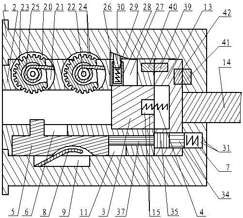
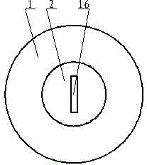
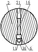
[0088] The electromechanical combination asynchronous interlocking additional tooth push anti-theft lock of the present invention mainly includes a lock body 1, a front lock core 2, a rear lock core 13, a connecting body 3, a return spring 4, a turning groove 6, a sliding hole 36, a sliding rod 37, a sliding Groove 11, sliding block 5, locking groove 10, expansion groove 9, expansion piece 8, locking spring 7, locking hole 31, connecting hole 12, connecting tongue 14, spring bearing hole 15, special key hole 16, Special key, locking head 34, top post 35, locking hole 33, turning hole 21, turning lock groove 20, gear wheel 23, shaft turning pin 22, mainspring spring 25, horizontal hole 27, longitudinal locking groove 26 , lock seat 28, lock column 30, push spring 29, main contact, auxiliary contact 40, fixed contact 41, rotating contact 42, electric insurance anti-theft system, asynchronous alarm system;

[0089] A front lock cylinder 2 and a rear lock cylinder 13 are installed...


PUM


Abstract

The invention discloses an electromechanically-combined, asynchronous interlocking and additional tooth-pushing anti-theft lock. A connector of the electromechanically-combined, asynchronous interlocking and additional tooth-pushing anti-theft lock is disconnected from a rear lock cylinder, a locking head locks the rear lock cylinder, an expansion sheet, a tooth rotation wheel and a lock column lock a front lock cylinder, the front lock cylinder and the rear lock cylinder are completely disconnected and asynchronously rotate for alarming, and an electronic remote control device is mounted in a power supply circuit of an electromagnet invisibly. The electromechanically-combined, asynchronous interlocking and additional tooth-pushing anti-theft lock integrates the functions of electromechanical interlocking invisibility, mechanical interlocking invisibility, connection invisibility of the front lock cylinder and the rear lock cylinder and asynchronous alarming, so that a thief cannot unlock an interlocking device and cannot rotate the rear lock cylinder; even if interlocking and self-locking parts are damaged in a barbarous way, only the front lock cylinder can be rotated while the rear lock cylinder cannot be rotated. Even if the thief drills out the front lock cylinder and the rear lock cylinder by using an electric hand drill and rotates a connection tongue by using a tool such as a clamp, a rotary contact is not in contact with a fixed contact, so that the power supply circuit of the electromagnet cannot be switched on; in addition, the electronic remote control device switches off the power supply circuit of the electromagnet, and a transverse safety lock pin cannot be unlocked, so that a thorough anti-theft effect can be achieved.

Description

technical field [0001] The invention relates to an electromechanical combined asynchronous interlocking additional tooth push anti-theft lock in the field of anti-theft locks. Background technique [0002] There are many kinds of anti-theft locks in use now, but basically all of them use the key to open the marble and then rotate to drive the deadbolt to open the anti-theft lock. Or the unlocking king can easily open the anti-theft lock. There are basically no anti-theft locks that thieves and unlocking kings cannot open. Contents of the invention [0003] The purpose of the present invention is to provide an anti-theft lock that combines asynchronous interlocking, asynchronous alarming, self-locking and electromechanical interlocking, high security, and no marbles, which cannot be opened by thieves and unlocking kings. Manufacture and its method. [0004] In order to achieve the above object, the electromechanical combination asynchronous interlocking additional tooth ...

Claims


Application Information

Patent Timeline
IPC IPC(8): E05B45/08E05B47/00E05B63/00E05B15/00E05B19/08E05B17/22
Inventor 徐園植其他发明人请求不公开姓名
Owner 徐园植
Why Eureka
Try Eureka