Valve spool transfer combined hydraulic shock excitation control valve

A control valve and composite technology, which is applied in the direction of fluid pressure actuators, servo motor components, mechanical equipment, etc., can solve the problem of large hydraulic power of the spool, difficult sealing of the spool, poor linearity of axial displacement adjustment flow, etc. problem, to achieve the effect of eliminating gaps, increasing accuracy and stability

Active Publication Date: 2015-04-29
日照纬润机电科技有限公司
View PDF5 Cites 14 Cited by
  • Summary
  • Abstract
  • Description
  • Claims
  • Application Information

AI Technical Summary

Problems solved by technology

However, there are many problems in its rotary valve structure, such as the difficulty and complexity of sealing the two shaft ends of the spool; the control of the axial displacement of the spool is unreliable, and a small amount of movement will occur in the axial direction; the matching relationship between the valve sleeve and the spool causes the valve The core is subjected to relatively large hydraulic force; the linearity of the axial displacement to adjust the flow is not good, etc.

Method used


Image

  • Valve spool transfer combined hydraulic shock excitation control valve
  • Valve spool transfer combined hydraulic shock excitation control valve
  • Valve spool transfer combined hydraulic shock excitation control valve

Examples


Embodiment Construction

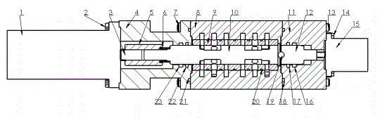
[0056] Such as figure 1 As shown, the spool transfer composite hydraulic excitation control valve 108 of the present invention includes a valve body 8, the inner cavity of the valve body 8 is fixedly provided with a valve sleeve 9, and a valve core 10 is movable inside the valve sleeve 9; the valve core 10 can Relative to the rotational movement of the valve sleeve 9, it can also move axially in the valve sleeve 9;

[0057] The right end of the spool 10 is offset against the steel ball 19; the plug 12 presses the right end of the spool 10 through the steel ball 19 to act as an axial positioning of the right end of the spool 10; the right end of the plug 12 is connected to the linear motor 15 through a screw; The rotation of the linear motor 15 drives the screw rod to move linearly left and right, and the screw rod drives the valve core 10 to move linearly left and right through the plug 12; The left end face of the valve body 8 is against the valve body 8, and an O-ring 18 is...


PUM


Abstract

The invention discloses a valve spool transfer combined hydraulic shock excitation control valve comprising a valve body, a valve spool, a valve sleeve, a rotary motor end cap, a connector, a spring, a plug, a linear motor and a rotary motor. The valve sleeve is fixedly arranged in an inner cavity of the valve body, and the valve spool is arranged in the valve spool movably; the valve spool can rotate relative to the valve sleeve as well as move axially in the valve sleeve. An oil outlet is opposite to an oil return opening in direction, axial fluid power is weakened along the direction of total force, analysis shows that the direction of total force faces the end of the linear motor, the gap of a lead screw during adjustment can be eliminated by combined action with a compression spring, and axial positioning during operation only depends on limit of the lead screw so as to improve accuracy and stability of axial positioning. The invention further discloses a hydraulic system adopting the valve spool transfer combined hydraulic shock excitation control valve.

Description

technical field [0001] The invention relates to a control valve, in particular to a spool transfer composite hydraulic vibration control valve. Background technique [0002] Auto parts, aerospace, ships, vibrating screens, vibrating pile hammers, vibrating screens and tamping machines have higher and higher requirements for products. In product performance testing, fatigue testing is required. Because vibration equipment can change the original state of the object being excited, such as the position and force, it has attracted more and more attention. Vibration equipment includes vibrator and vibrating table. The principle of vibrator and vibrating table is similar, and the key components are the excitation system. Vibrator can be divided into mechanical, electric, electro-hydraulic. The structure of the mechanical exciter is simple, the cost is low, the installation is convenient, the maintenance is easy, the amplitude does not change with the frequency change, but the ...

Claims


Application Information

Patent Timeline
Patent Type & Authority Applications(China)
IPC IPC(8): F15B13/02
CPCF15B13/02
Inventor 王维锐李星葛正石浩然
Owner 日照纬润机电科技有限公司
Why Eureka
Try Eureka