Buffer hydraulic cylinder

A buffer hydraulic cylinder and cylinder body technology, applied in the field of buffer hydraulic cylinders, can solve the problems that the buffer effect at the end of the stroke may not meet the requirements, affect the normal service life and precision of the hydraulic cylinder, and achieve novel overall structure, novel structure, and easy processing simple effect

Inactive Publication Date: 2015-04-29
CSIC ZHONGNAN EQUIP
View PDF7 Cites 21 Cited by
  • Summary
  • Abstract
  • Description
  • Claims
  • Application Information

AI Technical Summary

Problems solved by technology

However, due to the limitation of the internal space of the hydraulic cylinder, the cushioning effect at the end of the stroke may not meet the requirements
Especially when the hydraulic cylinder drives a large mass load, due to the...

Method used


Image

  • Buffer hydraulic cylinder
  • Buffer hydraulic cylinder
  • Buffer hydraulic cylinder

Examples


Embodiment Construction

[0022] The present invention will be described in detail below with reference to the accompanying drawings and examples.

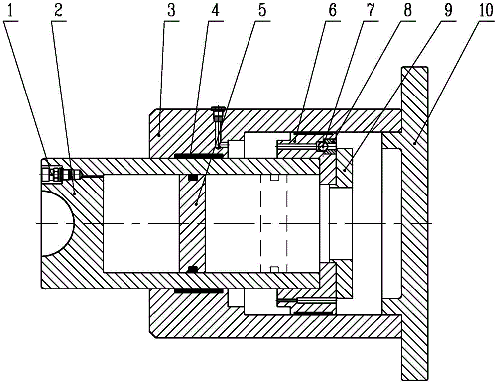
[0023] as attached figure 1 As shown, the present invention provides a buffer hydraulic cylinder, including an air charging valve 1, a plunger rod 2, a cylinder body 3, a seal 4, an air piston 5, a piston 6, a steel ball 7, a retaining ring 8, a gland 9, Cylinder bottom 10;

[0024] One end surface of the plunger rod 2 is processed with an arc groove, the arc groove matches the vibration part of the damped equipment, the end is equipped with an inflation valve 1, and the other end of the plunger rod 2 is cylindrical cavity;

[0025] as attached Figure 4 , 5 As shown in and 6, two groups of step through holes are processed on the piston surface of the piston 6, the first group of step through holes are steel ball installation valve holes, the steel ball is limited in the step hole by the retaining ring 8, and the retaining ring 8 and The steel ball is...


PUM


Abstract

The invention discloses a buffer hydraulic cylinder and belongs to the technical field of hydraulic cylinder structure. Two groups of stepped through holes are machined in the piston face of a piston, the first group of stepped through holes are steel ball installing valve holes, and steel balls are limited in the stepped through holes through retainer rings and can axially move in the stepped through holes. The other group of stepped through holes are variable-diameter holes. A plunger rod is matched with the front end of a cylinder body, the end located in the cylinder body, of the plunger rod, is sleeved with the piston, the outer circle circumference of the piston is matched with the inner wall of the cylinder body, the front end face of the piston is sleeved with a gland, the cylinder body is closed by the cylinder bottom, the piston divides the inner cavity of the cylinder body into two independent cavities including a rod cavity and a rodless cavity, and the rodless cavity is communicated with a column-shaped cavity of the plunger rod. An air piston is installed in the column-shaped cavity of the plunger rod. Sealing parts are installed on the matching faces between the plunger rod and the piston and the cylinder body. The oil input and oil output of the hydraulic cylinder are controlled without dependence on a hydraulic pump station, but a good buffer role can be played.

Description

technical field [0001] The invention relates to a buffer hydraulic cylinder, which belongs to the technical field of hydraulic cylinder structures. Background technique [0002] For hydraulic cylinders, especially double-acting hydraulic cylinders, in the case of fast operation, the return speed is generally faster, so it is necessary to install a buffer device at the end of the stroke. However, due to the limitation of the internal space of the hydraulic cylinder, the cushioning effect at the end of the stroke may not be able to meet the requirements. Especially when the hydraulic cylinder drives a large mass load, due to the excessive kinetic energy, there will be a violent collision between the piston, the bottom of the cylinder and the guide sleeve at the end of the stroke, which greatly affects the normal service life and accuracy of the hydraulic cylinder. Contents of the invention [0003] In view of this, the present invention provides a buffer hydraulic cylinder,...

Claims


Application Information

Patent Timeline
IPC IPC(8): F15B15/22F15B15/14
CPCF16F9/063F16F9/068F16F9/3214F16F9/3221F16F9/325F16F9/3405
Inventor 杜浩斌陈洁唐瑞刘建魁
Owner CSIC ZHONGNAN EQUIP
Why Eureka
Try Eureka