Electric control type pressure reduction water conveying valve

A water delivery valve and electronic control technology, applied in valve details, diaphragm valves, safety valves, etc., can solve problems such as affecting the water flow pressure reduction effect, damage to the water flow pressure reducing valve, and large volume of the pressure reducing valve, and achieve good sealing performance. and elasticity, preventing pressure instability, and improving sealing performance

Inactive Publication Date: 2015-04-29
NINGBO YAOFENG HYDRAULIC ELECTRICS
View PDF4 Cites 4 Cited by
  • Summary
  • Abstract
  • Description
  • Claims
  • Application Information

AI Technical Summary

Problems solved by technology

[0004] However, in the prior art, the valve body and the bonnet are mostly connected by screws, and the influence of water flow impurities is not considered. The pressure reducing valve has a large volume, high production cost, low sensitivity, and low sealing performance. It is easy to cause water flow impurities to enter the water flow pressure reducing valve, which will affect the water flow pressure reducing effect and damage the water flow pressure reducing valve.

Method used


Image

  • Electric control type pressure reduction water conveying valve
  • Electric control type pressure reduction water conveying valve
  • Electric control type pressure reduction water conveying valve

Examples


Embodiment Construction

[0026] The following are specific embodiments of the present invention and in conjunction with the accompanying drawings, the technical solutions of the present invention are further described, but the present invention is not limited to these embodiments.

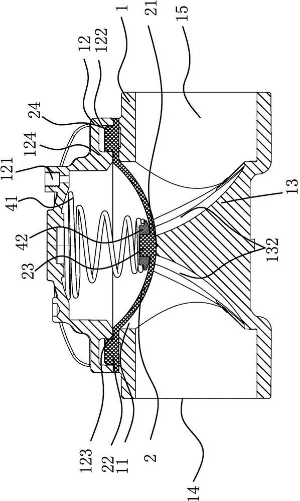
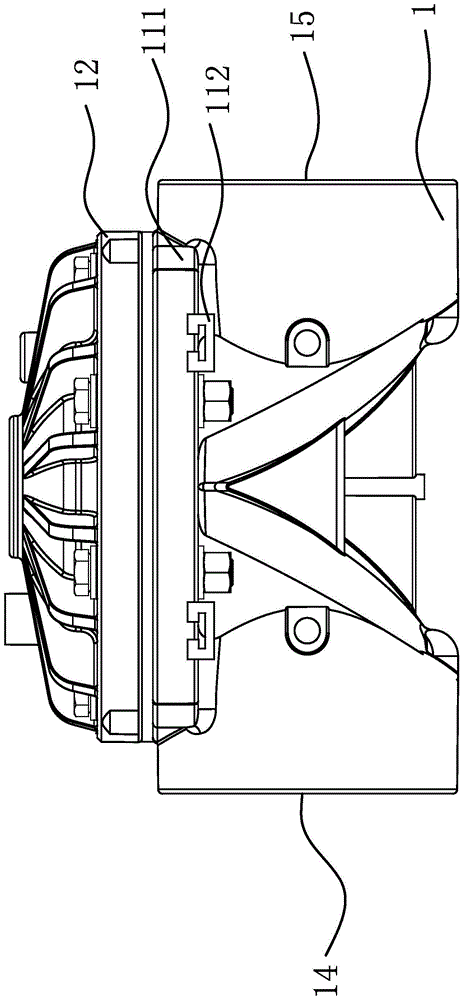
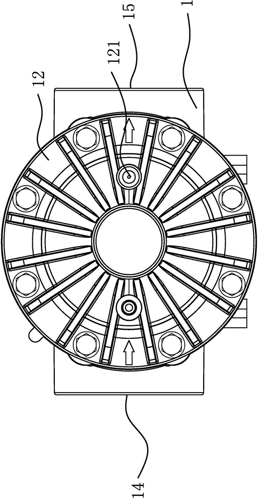
[0027] like figure 1 and figure 2 As shown, the present invention includes a valve body 1 with a cover 11 and an arched valve cover 12 installed on the cover 11, the outer edge of the cover 11 extends along the vertical axis of the cover 11 to form a cover plate 111, the valve The outer edge of the cover 12 extends along the direction perpendicular to the axis of the valve cover 12 to form a fixed part 124, which is installed on the cover plate 111, and the inner surface of the valve body 1 protrudes to form a sealing platform 13, and the sealing platform 13 is on the cover 11. Just below the valve cover 12 and the valve body 1, a cup 2 is installed. The outer edge of the cup 2 extends along the direction perpendicular t...


PUM


Abstract

The invention belongs to the mechanical technical field and relates to fluid pressure execution mechanisms, particularly to an electric control type pressure reduction water conveying valve. The problems that the existing electric control type pressure reduction water conveying valve is poor in sealing performance and low in sensitivity are solved. The electric control type pressure reduction water conveying valve comprises a valve body and a valve cover, wherein the valve body comprises a cover opening and the valve cover is arranged on the valve opening; the valve cover is in an arched shape; a sealing platform is formed on the inner surface of the valve body in a protruding mode; a center line of the sealing platform and the axis of the cover opening are located on the same straight line; a cup is arranged between the valve cover and the valve body; circular-arc-shaped first reinforcing ribs are formed on the outer surface of the cup in a protruding mode; the first reinforcing ribs can abut against the sealing platform; a spring assembly is arranged between the valve cover and the cup; one end of the spring assembly is arranged on the cup; the other end of the spring assembly abuts against the inner surface of the valve cover. According to the electric control type pressure reduction water conveying valve, the sealing performance is good, the pressure in the valve body is stable, and the sensitivity is high.

Description

technical field [0001] The invention relates to a fluid pressure actuator, in particular to an electronically controlled decompression water delivery valve. Background technique [0002] The pressure reducing valve is a valve that reduces the inlet pressure to a certain required outlet pressure and relies on the energy of the medium itself to automatically maintain the outlet pressure. From the point of view of fluid mechanics, the pressure reducing valve is a throttling element whose local resistance can be changed, that is, by changing the throttling area, the flow velocity and the kinetic energy of the fluid are changed, resulting in different pressure losses, so as to achieve the purpose of decompression. Then rely on the adjustment of the control and regulation system to balance the fluctuation of the post-valve pressure with the spring force, so that the post-valve pressure remains constant within a certain error range. [0003] The pressure reducing valve is a specia...

Claims


Application Information

Patent Timeline
Patent Type & Authority Applications(China)
IPC IPC(8): F16K7/17F16K17/30F16K27/08F16K27/00
CPCF16K7/17F16K17/30F16K27/00F16K27/08
Inventor 张明耀
Owner NINGBO YAOFENG HYDRAULIC ELECTRICS
Why Eureka
Try Eureka