Shockproof packaging box of optical splitter

An optical splitter and packaging box technology, applied in the fiber mechanical structure and other directions, can solve the problems of the steel pipe and the packaging box falling off, the impact force is large, and it is easy to make mistakes, so as to avoid pulling or breaking the optical fiber and reducing the impact. strength and damage avoidance

Active Publication Date: 2014-11-26
ZHONGTIAN BROADBAND TECH +1
View PDF8 Cites 0 Cited by
  • Summary
  • Abstract
  • Description
  • Claims
  • Application Information

AI Technical Summary

Problems solved by technology

[0005] 1. AB glue is mixed by A glue and B glue according to the weight ratio of 1:1. When preparing glue, it is easy to make a wrong ratio and cause the glue to not stick firmly.
[0006] 2. In the process of operation, the optical cable is easy to be glued. Since the AB glue solidifies on the optical cable and cannot be wiped off, the PLC square box is directly scrapped.
[0007] 3. In the traditional process, because the optical fiber is directly coiled in the square box, the bending radius of the optical fiber may be too small or twisted, resulting in unqualified PLC optical performance
Because the AB glue is very hard after curing, if the PLC is defective when sealing the steel pipe or the square box, it was not detected at that time, and it is difficult to repair it later
[0009] 5. In the traditional process, because it is only loosely placed in a square box, the optical fiber shakes in the box during the drop test, causing the optical fiber to be messy, which leads to the PLC optical performance exceeding the standard.
[0010] 6. The AB glue is very hard and brittle after curing. When the cassette PLC is dropped from a height of 1.8 meters, the impact force is very large, causing the steel pipe and the packaging box to fall off. When it falls again, the steel pipe shakes, causing the steel pipe to pull the optical fiber, and finally Cause IL change amount greater than 0.5dB or single fiber break
[0018] Through the patent search, the above patent documents did not disclose the invention, and did not destroy the novelty of the invention

Method used


Image

  • Shockproof packaging box of optical splitter
  • Shockproof packaging box of optical splitter
  • Shockproof packaging box of optical splitter

Examples


Embodiment 1

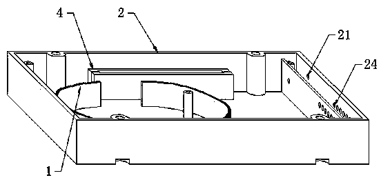
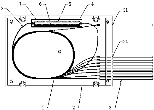
[0050] Such as Figure 1-2 As shown, the present invention creates a shockproof packaging box for an optical splitter, which includes a packaging box 2, an optical fiber inlet hole 21 is provided on the right end surface of the packaging box 2, and a row of optical fiber outlet holes 24 is provided on the right end surface of the packaging box 2; An optical fiber protection device 1 is provided at the center of the inner surface of the packaging box 2, and a mounting seat 4 is provided on the inner surface of the packaging box 2 near the optical fiber inlet hole 21. The mounting seat 4 is equipped with a steel pipe sleeve 5, and the steel pipe sleeve 5 A buffer and shockproof layer 7 is arranged between the interior and the planar optical waveguide splitter 6;

[0051] In actual use, such as figure 2 As shown, a single optical fiber is introduced from the optical fiber inlet hole 21, first wound around the optical fiber protection device 1, and then connected to the planar o...

Embodiment 2

[0054] In a preferred implementation situation, with respect to Example 1, such as Figure 3-5 As shown, the internal structure of the mounting seat 4 is vase-shaped, the size of the opening end of the upper end of the vase-shaped upper end is larger than the size of the bottom end, the upper end of the internal shape is an outer convex arc surface I41, and the middle section is an inner concave arc surface 42 , the bottom section is the convex arc surface II43; the outer shape of the above-mentioned steel pipe sleeve 5 is the convex arc surface III51, and the arc degree of the convex arc surface III51 and the concave arc surface 42 are kept co-operate.

[0055] In actual use, the steel pipe sleeve 5 needs to be installed in the inner cavity of the mounting base 4 . During the installation process, the outer convex arc surface III51 of the steel pipe sleeve 5 first contacts the outer convex arc surface I41 on the upper part of the mounting seat 4. Through extrusion, the inner...

Embodiment 3

[0058] In a preferred implementation situation, with respect to embodiment 2, such as Figure 6-8 As shown, the mounting base 4 is provided with more than three cover mounting bases 44 for mounting the cover plate 9, the width b of the above cover plate 9 is 6-10 mm, and the above cover plate 9 includes The rotating end 91 and the fixed end 93; the above-mentioned rotating end 91 is hinged with the cover mounting seat 44 through the rotating shaft 92, and the cross section of the rotating end 91 is arc-shaped; the above-mentioned fixed end 93 lower surface is installed with a The thimble 94 is used to rigidly fix the fixed end 93 , and the mounting base 4 is provided with a slot 45 matched with the thimble 94 .

[0059] The technical problem to be solved in Embodiment 3 is: the steel pipe sleeve 5 can be further tightened by providing the cover plate mounting seat 44 for installing the cover plate 9, so that the steel pipe sleeve 5 cannot be displaced regardless of the impact ...


PUM


Abstract

The invention discloses a shockproof packaging box of an optical splitter. The shockproof packaging box of the optical splitter comprises a packaging box body. An optical fiber coil-in hole is formed in the right end surface of the packaging box body, and a row of optical fiber coil-out holes are formed in the right end surface of the packaging box body. An optical fiber protector is arranged in the center of the inner surface of the packaging box body. An installation base is arranged on the portion, close to the optical fiber coil-in hole, of the inner surface of the packaging box body. A steel pipe sleeve is installed on the installation base in a supporting mode, and a buffering shockproof layer is arranged between the interior of the steel pipe sleeve and the planar light wave circuit splitter and attached to the inner surface of the steel pipe sleeve closely. According to the shockproof packaging box of the optical splitter, through the improvement of the internal structure of the optical splitter, the optical splitter can conform to 'technical requirements for passive optical splitter of China telecom' when mechanical performance tests of the optical splitter are carried out, and the service life of the optical splitter is prolonged effectively.

Description

technical field [0001] The invention relates to the field of shockproof devices, in particular to a shockproof packaging box for an optical splitter. Background technique [0002] In the optical communication industry, box-type PLC is a widely used passive device. In the production process of box-type PLC (Planar Light wave Circuit Splitter, planar optical waveguide splitter), the bare device PLC is first packaged in a steel pipe , and then package the packaged PLC into a square box. [0003] In the "Technical Requirements for China Telecom Passive Optical Splitter", the mechanical performance requirements of the optical splitter: the box PLC needs to be dropped from a height of 1.8m, 3 axes, 8 times in each axis, 5 cycles, After the fall, the change in IL is less than 0.5dB (dB (Decibel, decibel) is a pure counting unit, which is intended to represent the ratio of two quantities). [0004] In the existing production process, the PLC with the steel pipe is first fixed to ...

Claims


Application Information

Patent Timeline
Patent Type & Authority Patents(China)
IPC IPC(8): G02B6/44
Inventor 彭延斌余朝晃唐琳
Owner ZHONGTIAN BROADBAND TECH
Why Eureka
Try Eureka