Electric hydraulic excavator special for tunnel

A technology for hydraulic excavators and excavators, which is applied to mechanically driven excavators/dredgers, etc., can solve the problems of large turning radius of the manipulator, and achieve the effects of reducing energy consumption, reducing the amount of expansion and contraction, and reducing carbon emissions.

Pending Publication Date: 2022-02-18
龙道恒
View PDF0 Cites 0 Cited by
  • Summary
  • Abstract
  • Description
  • Claims
  • Application Information

AI Technical Summary

Problems solved by technology

[0006] The invention provides an electric hydraulic excavator dedicated to tunnels, which solves the problem of large turning radius of the mechanical arm

Method used


Image

  • Electric hydraulic excavator special for tunnel
  • Electric hydraulic excavator special for tunnel
  • Electric hydraulic excavator special for tunnel

Examples


no. 1 example

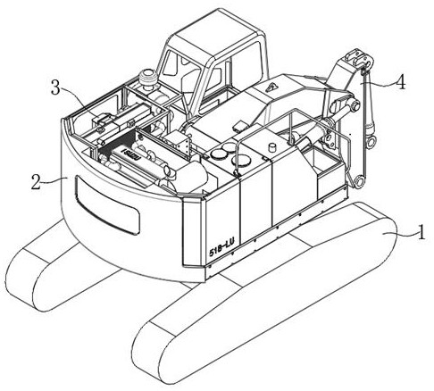
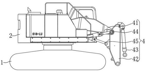
[0039] Please refer to figure 1 , figure 2 ,in, figure 1 A schematic structural view of the first embodiment of the tunnel-specific electro-hydraulic excavator provided by the present invention; figure 2 It is a schematic diagram of the side structure of the electro-hydraulic excavator dedicated to tunnels provided by the present invention. Electro-hydraulic excavators for tunnels, including:

[0040] The walking X-frame assembly 1 for moving on the ground, the upper frame assembly 2 as the external main structure of the excavator, the power output assembly 3 for providing power support for the excavator, and the power output assembly 3 for installing and driving the excavator The mechanical arm assembly 4 for workpiece movement;

[0041] The mechanical arm assembly 4 includes a first support arm 41, the first support arm 41 rotates on the upper frame assembly 2, and the maximum rotation height of the first support arm 41 is less than or equal to the upper frame assembly...

no. 2 example

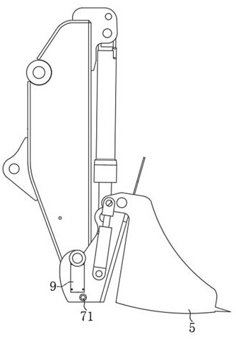
[0055] Please refer to image 3 , Figure 4 and Figure 5 , based on the first embodiment of the present invention is an electro-hydraulic excavator dedicated to tunnels, the second embodiment of the present invention provides another electro-hydraulic excavator dedicated to tunnels, wherein the second embodiment does not hinder the first embodiment independent implementation of technical solutions.

[0056] Specifically, the present invention provides another electro-hydraulic excavator dedicated to tunnels, which differs in that:

[0057] An excavation bucket 5 is installed on the bottom of the second support arm 42, and both sides of the exterior of the excavation bucket 5 are provided with movable grooves 6, and the outer side of the movable groove 6 extends to the inner side of the excavation bucket 5. Pass through the active slot 6 so that the external connecting piece connects the top of the excavating bucket 5 with the second support arm 42 .

[0058] The two movab...

no. 3 example

[0067] Please refer to Figure 5 , based on the first embodiment of the present invention is an electro-hydraulic excavator dedicated to tunnels, the third embodiment of the present invention provides another electro-hydraulic excavator dedicated to tunnels, wherein the third embodiment does not hinder the first embodiment independent implementation of technical solutions.

[0068] Specifically, the present invention provides another electro-hydraulic excavator dedicated to tunnels, which differs in that:

[0069] The top of the locking block 73 is provided with a buffer structure 8, the buffer structure 8 includes a movable block 81, the movable block 81 slides on the top of the locking block 73, and the left and right sides of the movable block 81 are Both sides are fixedly equipped with a connecting rod 82, the outside of the connecting rod 82 is sleeved with an elastic member 83, the outside of the connecting rod 82 is slidably connected with the inside of the locking blo...


PUM


Abstract

The invention provides an electric hydraulic excavator special for a tunnel. The electric hydraulic excavator special for the tunnel comprises a walking X frame assembly used for moving on the ground, an upper rack assembly serving as an external main body structure of the excavator, a power output assembly used for providing power support for the excavator and a mechanical arm assembly used for installing and driving an excavating workpiece to move. According to the electric hydraulic excavator special for the tunnel, the mechanical arm assembly is arranged and mainly used for achieving the excavation effect on the interior of the tunnel; the first supporting arm and the second supporting arm which are equal in length are arranged, so that the gyration radius of the first supporting arm and the gyration radius of the second supporting arm are further reduced; the first hydraulic assembly and the second hydraulic assembly are used for driving the first supporting arm and the second supporting arm to rotate respectively, so that the stretching amount of the first supporting arm and the second supporting arm is greatly reduced, and energy consumption is further reduced; and in addition, the maximum stretching amount of the first supporting arm and the second supporting arm is reduced, and the first supporting arm and the second supporting arm can freely move in the tunnel.

Description

technical field [0001] The invention relates to the field of excavators, in particular to an electro-hydraulic excavator dedicated to tunnels. Background technique [0002] Tunnels are engineering buildings buried in the ground, and are a form of human use of underground space. Tunnels can be divided into traffic tunnels, hydraulic tunnels, municipal tunnels, mine tunnels, and military tunnels. [0003] During the construction of the tunnel, a lot of construction equipment needs to be used, and the excavator is the most common one, which can excavate the non-explosive earthwork of the tunnel, and is generally composed of a walking mechanism, a machine body and an excavating mechanism. [0004] In the related art, the traditional excavator, due to the high height and length of the mechanical arm of the excavating mechanism, is easily restricted in the tunnel with limited space, which reduces the overall mobility of the excavator and cannot realize full-section excavation. An...

Claims


Application Information

Patent Timeline
Patent Type & Authority Applications(China)
IPC IPC(8): E02F3/28E02F3/34
CPCE02F3/28E02F3/34
Inventor 龙道恒龙道谋龙成龙烨
Owner 龙道恒
Why Eureka
Try Eureka