

Heat tracing turbulent layer fluidized drag-reducing flow conveying pipe and method thereof
A drag-reducing fluid and turbulent layer technology, applied in the direction of fluid flow, pipeline heating/cooling, pipes, etc., can solve the problem of uncontrolled pipeline flow, achieve high heating power, high tensile strength, and good energy-saving effect
- Summary
- Abstract
- Description
- Claims
- Application Information
AI Technical Summary
Problems solved by technology
Method used
Image

Examples
Embodiment Construction
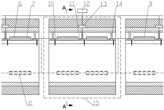
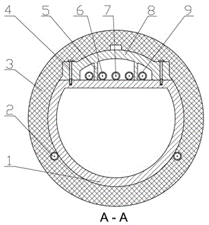
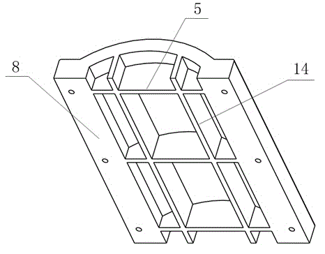
[0018] as attached figure 1 , 2 , 3, the heat-tracing type turbulent laminar fluidization drag-reducing fluid transport pipeline is composed of a plurality of single-section transportation pipelines 15 and a general controller 12, and the single-section transportation pipeline 15 includes an arcuate pipeline 1, a fluid electric heating pipe 2. Insulation layer 3, bolts 4, axial ribs 5, pipe wall electric heat tracing pipe 6, insulated wire 7, pipe upper cover 8, heat tracing steel pipe 9, fluid temperature monitoring device 10, wall temperature monitoring device 11, temperature control device 13 and radial ribs 14; the arched pipe is connected by welding or flange, the cross section of the arched pipe is a bow with the chord at the top, and the arc length is longer than the semicircle, and the upper cover 8 of the pipe is connected to the upper surface of the bowed pipe chord through the bolts 4 on both sides. The inner side of the upper cover of the pipe is provided with an ...
PUM
 Abstract
Description
Claims
Application Information