
Head lamp for vehicle

A vehicle and headlight technology, applied in the field of headlights, can solve the problems of reduced luminous efficiency, increased weight and cost, and increased overall optical size

Inactive Publication Date: 2015-04-29
HYUNDAI MOTOR CO LTD +1
View PDF7 Cites 20 Cited by
  • Summary
  • Abstract
  • Description
  • Claims
  • Application Information

AI Technical Summary

Problems solved by technology

Existing laser optics cause light losses due to light scattered towards the sides and rear of the phosphor 2, thus reducing luminous efficiency
[0007] In addition, the reflector 4 of the existing laser optical system is separately arranged outside the laser light source module 5, so that the total size of the optical size will increase, so the weight and cost will increase

Method used


Image

  • Head lamp for vehicle
  • Head lamp for vehicle
  • Head lamp for vehicle

Examples


Embodiment Construction

[0026] Hereinafter, a headlamp for a vehicle according to an exemplary embodiment of the present inventive concept will be described with reference to the accompanying drawings.

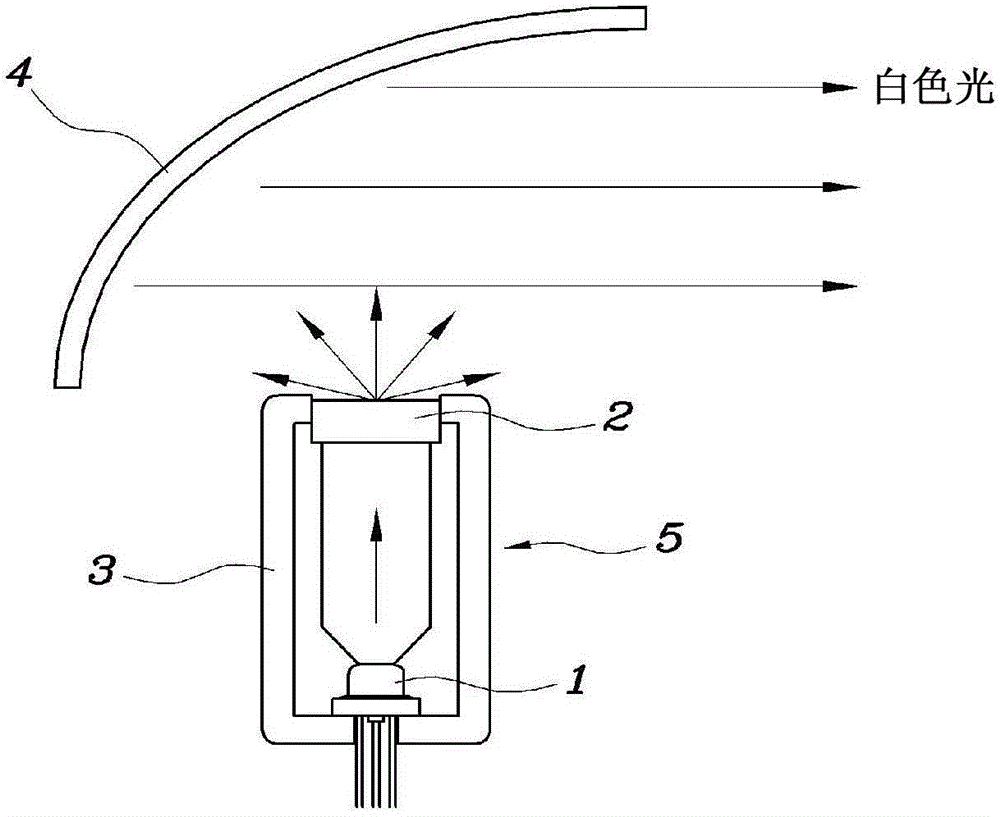
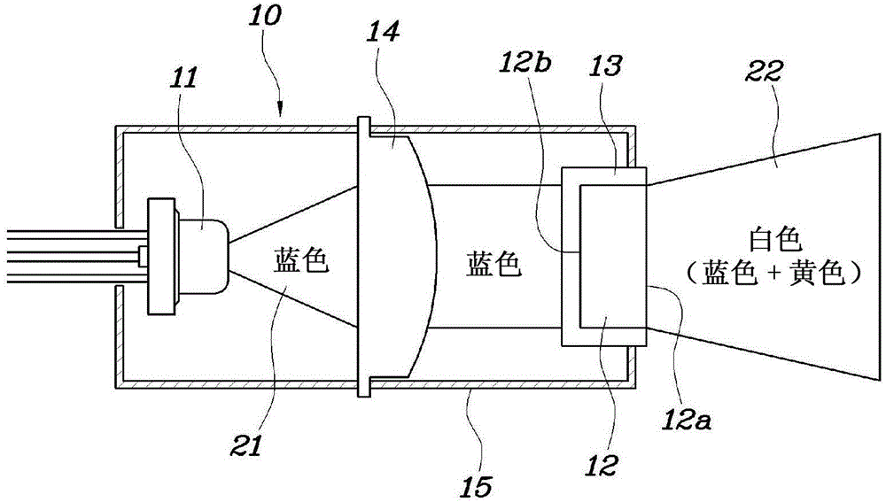
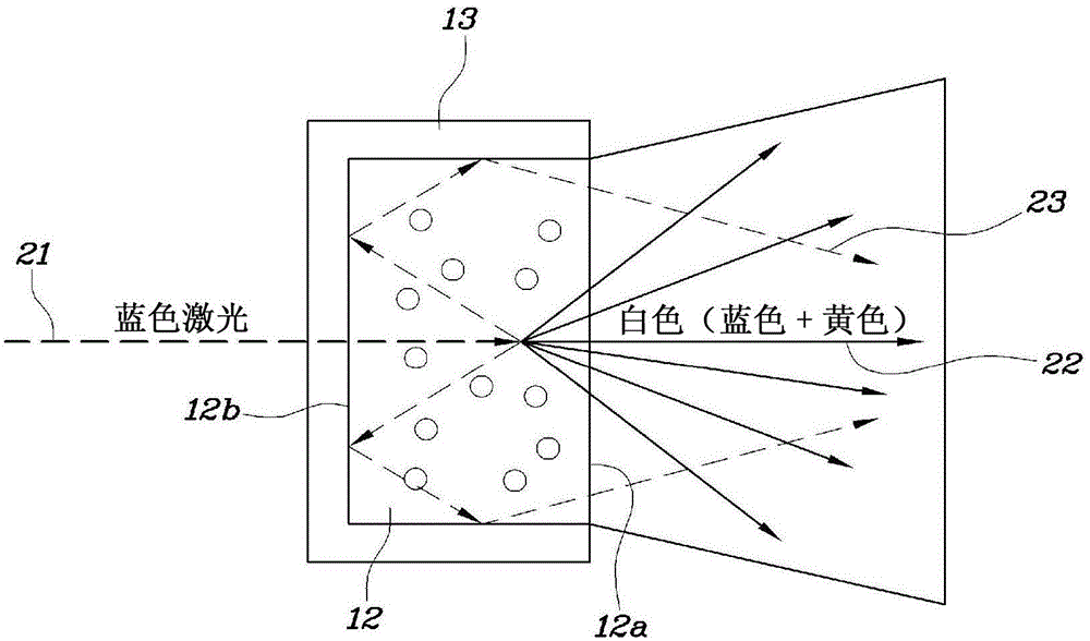
[0027] refer to figure 2 and image 3 , the headlamp for a vehicle according to an exemplary embodiment of the present inventive concept includes a laser light source module 10 . The laser light source module 10 includes a laser diode 11 that generates a laser beam 21 in the blue wavelength range (typically a short wavelength of 450 nm). Phosphor 12 is installed in front of laser diode 11 and reacts with light from laser diode 11 to output white light 22 . The short-pass filter 13 is coupled to the phosphor 12 to transmit the laser beam 21 from the laser diode 11 to the phosphor 12 and to avoid the laser beam 21 incident on the phosphor 12 from the phosphor 12 Light scattered in the direction of the light-emitting surface 12 a is reflected back to the phosphor 12 .

[0028] Here, the short wave ...


PUM


Abstract

A head lamp for a vehicle includes a laser light source module. The laser light source module comprises a laser diode generating a laser beam. A phosphor is mounted in front of the laser diode to react to light from the laser diode to output white light. A short wave pass filter is coupled with the phosphor to transmit a laser beam from the laser diode to the phosphor and retro-reflect light scattered in remaining directions avoiding a light emitting surface of the phosphor among the laser beam incident on the phosphor to the phosphor.

Description

technical field [0001] The present disclosure relates to a head lamp for a vehicle, and more particularly, to a technique for a head lamp for a vehicle using a laser diode as a light source. Background technique [0002] Headlamps for vehicles illuminate the front of the vehicle to help drivers see the area ahead, wherein halogen, high intensity discharge (HID), LED diodes, etc. are used as light sources. [0003] However, halogen, HID, LED diodes, etc. consume high power and thus have low luminous efficiency. In particular, the overall size of an optical system including a light source and lenses of halogen, HID, and LED diodes is large, and thus, a degree of freedom in design is reduced and weight is increased. [0004] Recently, a headlamp using an environmentally friendly laser diode having a long service life and high luminous efficiency as a light source has been developed. [0005] refer to figure 1 , an existing optical system comprising a laser diode 1 generating...

Claims


Application Information

Patent Timeline
Patent Type & Authority Applications(China)
IPC IPC(8): F21S8/10F21V9/08F21V13/00F21W101/02F21W101/10F21Y101/02F21W107/10
CPCF21S41/14F21S41/285F21S41/16F21S41/176B60Q1/04
Inventor 安秉石李泰远
Owner HYUNDAI MOTOR CO LTD
Learn More