
Solar water heater

A solar water heater and water tank technology, which is applied in solar collectors, solar thermal energy, solar thermal power generation, etc., can solve problems such as safety accidents and unsafe circuits, and achieve the effects of ensuring safety, improving efficiency, and avoiding material waste.

Inactive Publication Date: 2015-04-29
南通奥特机械设备有限公司
View PDF7 Cites 1 Cited by
  • Summary
  • Abstract
  • Description
  • Claims
  • Application Information

AI Technical Summary

Problems solved by technology

[0002] At present, solar water heaters in the prior art are basically a water tank equipped with a set of vacuum tubes, relying solely on solar energy for heating, and recently relying on solar energy cannot provide enough hot water for cloudy days In this case, improve the use of a water heater equipped with two water tanks. On the one hand, the two water tanks are to solve the problem of increasing the water capacity when the sun is sufficient. The purpose, the patent number is CN201220063699.2 discloses a kind of fast heating and energy-saving solar water heater water tank, which is two inner water tanks that are not completely separated, which solves the above-mentioned problems, but we all know that the reason why solar water heaters are so common is that Because it relies on the energy of the sun, it is a very environmentally friendly and low-carbon device. If the solar water heater is also made into an electric heating form, it seems to solve the problem of no hot water on cloudy days. In this way, the solar water heater and ordinary household What is the difference between electric water heaters? They all need to rely on electricity consumption for heating, and solar water heaters are placed outside. Every day, the wind, rain, and sun exposure are not safe for the circuit. Especially in the weather of thunder and lightning, it is very easy to cause safety accidents.

Method used


Image

  • Solar water heater

Examples


Embodiment

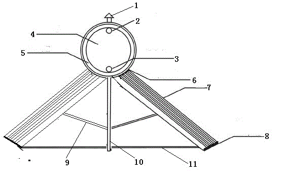
[0027] Such as figure 1 As shown, a solar water heater in this embodiment includes: an overflow port 2, a water inlet 3, a water tank 4, an insulation layer 5, a vacuum tube 7, a plastic support 8, a horizontal support 9, a main support 10, and a base 11;

[0028] The overflow 2 and the water inlet 3 are located on the same side of the water tank 4, the overflow 2 is located at the top of the side of the water tank 4, and the water inlet 3 is located at the bottom of the side of the water tank 4;

[0029] Described insulation layer 5 is shell, insulation material, liner respectively from outside to inside;

[0030] The vacuum tube 7 includes two groups, which are arranged symmetrically with respect to the main support 10;

[0031] Described horizontal bracket 9 connects the middle part of vacuum tube 7 and main bracket 10 and is suspended in the air at an obtuse angle;

[0032] The base 11 is connected to the bottom of the vacuum tube 7 and the main support 10 and arranged...


PUM


Abstract

The invention discloses a solar water heater. The solar water heater comprises an overflow opening, a water inlet, a water tank, an insulation layer, vacuum tubes, a plastic holder, a transverse supporting frame, a main supporting frame and a base. The overflow opening and the water inlet are arranged in the same side of the water tank, the overflow opening is arranged in the top of the side of the water tank, and the water inlet is arranged in the bottom of the side of the water tank. The insulation layer comprises a housing, an insulation material and an interior from outside to inside. The two groups of vacuum tubes are symmetrically arranged relative to the main supporting frame. The transverse supporting frame is connected to the vacuum tubes and the central portion of the main supporting frame and suspended at an obtuse angle. The base is connected to the vacuum tubes and the bottom of the main supporting frame and horizontally arranged to the ground. The plastic holder is arranged at the bottoms of the vacuum tubes. The solar water heater is reasonable in design and simple in structure, still has a low-carbon environment-friendly function, prolongs direct sun lighting time and improves the heating efficiency.

Description

technical field [0001] The invention relates to the field of water heaters, in particular to a solar water heater. Background technique [0002] At present, the solar water heater in the prior art is basically a water tank equipped with a group of vacuum tubes, which is heated solely by solar energy. Recently, for the situation that solar energy cannot provide enough hot water in cloudy days, a water heater equipped with two water tanks has been improved and used. On the one hand, the water tank is to solve the problem of increasing the water capacity when the sun is sufficient, and on the other hand, it is also hoped that one of the water tanks can be heated by electricity to achieve hot water in cloudy days. The patent number is CN201220063699.2, which discloses a fast heating The energy-saving solar water heater water tank is two inner water tanks that are not completely separated, which solves the above problems, but we all know that the reason why solar water heaters a...

Claims


Application Information

Patent Timeline
IPC IPC(8): F24J2/24F24J2/46F24J2/51F24S10/70
CPCY02E10/44
Inventor 陈金生
Owner 南通奥特机械设备有限公司
Learn More