
A movement assembly accuracy detection jig and detection method thereof

A technology for assembly accuracy and detection fixtures, which is applied to measuring devices, instruments, etc., can solve the problems of the detection accuracy not meeting the design requirements, the difficulty of batch detection, and high labor intensity, so as to reduce the labor intensity of workers, simplify the structure, improve The effect of factory pass rate

Active Publication Date: 2017-06-20
DALIAN YUN MING AUTOMATION TECH
View PDF5 Cites 0 Cited by
  • Summary
  • Abstract
  • Description
  • Claims
  • Application Information

AI Technical Summary

Problems solved by technology

In the traditional process, manual and visual methods are usually used to test the installation accuracy of the resin buckle, which is labor-intensive, and the detection efficiency is low, the detection accuracy cannot meet the design requirements, and batch detection is difficult

Method used


Image

  • A movement assembly accuracy detection jig and detection method thereof
  • A movement assembly accuracy detection jig and detection method thereof

Examples


Embodiment Construction

[0022] Embodiments of the present invention will be described in detail below in conjunction with the accompanying drawings.

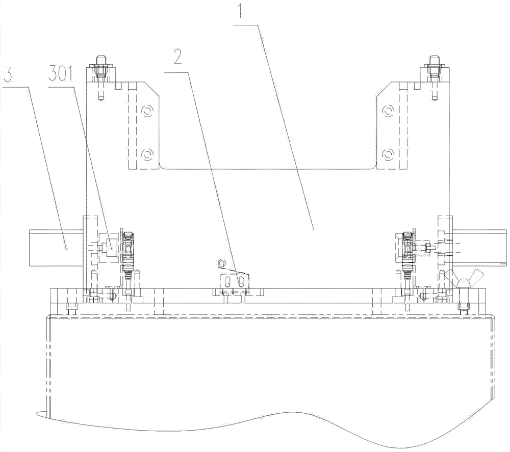
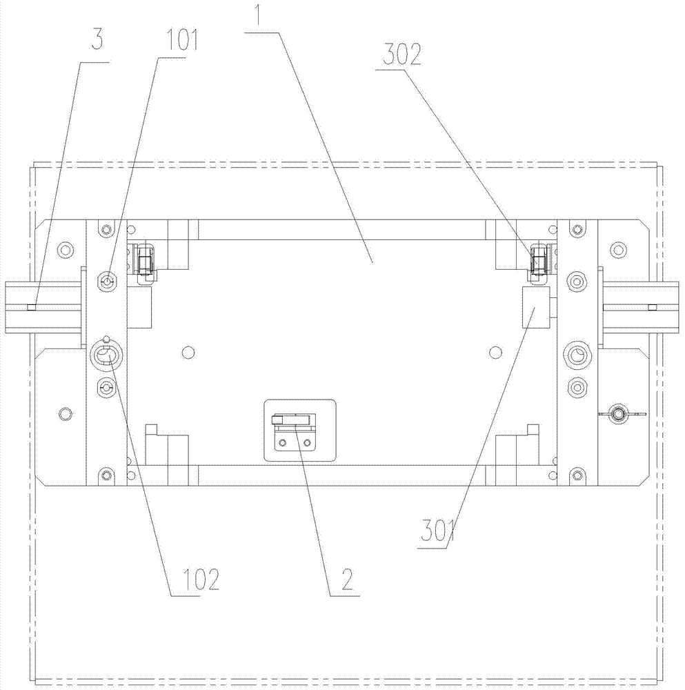
[0023] refer to figure 1 and figure 2 , the present invention provides a movement assembly accuracy detection jig, which includes a placement bracket 1 for placing the movement, the placement bracket 1 includes a bottom plate, two side plates vertically installed on the bottom plate, and two side plates fixed on both sides The top is also used to connect the connecting plate of the two side plates, and the accommodation cavity for accommodating the movement is formed between the two side plates, and the connecting plate is used to support the whole movement. The test needle 101 and the positioning pin 102 corresponding to the pin hole on the movement are provided with a micro switch 2 for detecting whether the movement is installed in place on the upper bottom surface of the bottom plate. In this embodiment, the micro switch is an Omron The switch i...


PUM


Abstract

The invention provides a machine core assembling accuracy detection jig. The machine core assembling accuracy detection jig comprises a placing support used for placing a machine core, test pins corresponding to locating holes in the machine core and a locating pin corresponding to a pin hole in the machine core are arranged on the top of the placing support. A microswitch used for detecting whether the machine core is mounted in place or not and proximity sensors used for detecting whether a resin button is mounted on the machine core or not are arranged on the bottom face of the placing support. Detection cylinders are arranged at the two ends of the placing support, the output ends of the detection cylinders are fixedly connected with detection sleeves capable of being arranged on the machine core in a sleeving mode, and a cylinder sensor capable of detecting whether each detection cylinder stretches in place or not is arranged on one side of the detection cylinder. The microswitch, the proximity switches and the cylinder sensors are connected with a PLC. The machine core assembling accuracy detection jig is simple in structure, convenient to use, fast and efficient in detection, high in precision, and capable of greatly lowering the labor intensity of workers and improving the factory leaving pass rate.

Description

technical field [0001] The invention relates to a detection jig, in particular to a detection jig for assembly accuracy of a movement and a detection method thereof. Background technique [0002] In the prior art, there is a movement, which has a pin hole and a mounting hole, and resin buckles are installed on both sides, and the installation accuracy of the resin buckle has extremely high requirements. In the traditional process, manual and visual methods are usually used to test the installation accuracy of the resin buckle, which is labor-intensive, and the detection efficiency is low, the detection accuracy cannot meet the design requirements, and batch detection is difficult. Contents of the invention [0003] 【1】Technical problems to be solved [0004] The technical problem to be solved by the present invention is to provide a jig and a detection method for automatic detection, which is convenient, fast, and efficient for the detection of movement assembly accuracy....

Claims


Application Information

Patent Timeline
Patent Type & Authority Patents(China)
IPC IPC(8): G01B21/00
CPCG01B21/00
Inventor 王承刚安耀伟田志涛
Owner DALIAN YUN MING AUTOMATION TECH
Learn More