Fluorescence observation device, base frame and fluorescence microscope with multiple groups of different-angle light sources

An observation device and multi-angle technology, applied in microscopes, fluorescence/phosphorescence, optics, etc., can solve problems such as difficulty in reducing development costs, poor experimental results, and unsatisfactory results. The temperature is not easy to rise, reduce production costs, and reduce interference. Effect

Inactive Publication Date: 2017-10-13
LUMOS TECH
View PDF8 Cites 1 Cited by
  • Summary
  • Abstract
  • Description
  • Claims
  • Application Information

AI Technical Summary

Problems solved by technology

[0011] Although the above direction can make the illumination uniform and increase the convenience of observation, if the heat generated by the light source assembly does not have a good heat dissipation pipe, so that when the heat is left in the light-shielding chamber, the temperature may still rise, resulting in the final The experimental results are not good, and in order to obtain the best lighting angle, it is necessary to design an additional mechanical or electronic adjustment structure. It is difficult to reduce the development cost, and it is prone to damage after long-term use. Additional maintenance is required, so there is still room for improvement.

Method used


Image

  • Fluorescence observation device, base frame and fluorescence microscope with multiple groups of different-angle light sources
  • Fluorescence observation device, base frame and fluorescence microscope with multiple groups of different-angle light sources
  • Fluorescence observation device, base frame and fluorescence microscope with multiple groups of different-angle light sources

Examples


Embodiment Construction

[0058] The aforementioned and other technical contents, features and functions of the present invention will be clearly presented in the following detailed description of the preferred embodiments in conjunction with the accompanying drawings; the same or similar elements will be marked with similar symbols.

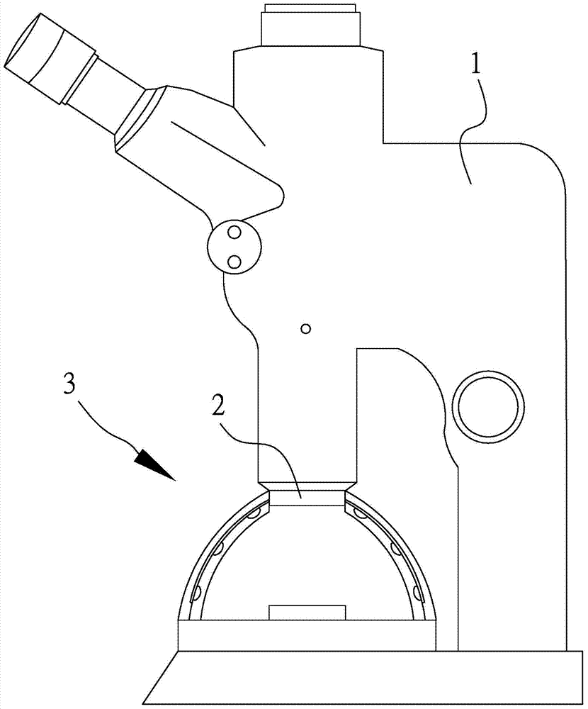
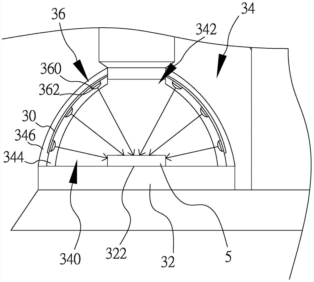
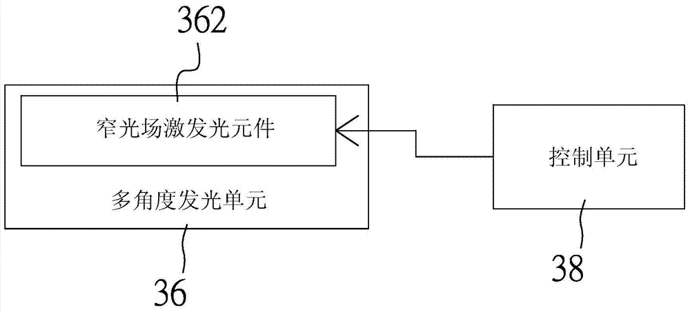
[0059] Fluorescence micro-optical device of the present invention, such as figure 1 , figure 2 and image 3 As shown, it is for detecting a fluorescent object to be observed 5, mainly including a body 1, an objective lens 2 and a fluorescence observation device 3, wherein the objective lens 2 is installed on the body 1, and the fluorescence observation device 3 includes a base 32, The cover body 34, the multi-angle light emitting unit 36, the control unit 38 and the flexible driving board 30, while the base 32 has a carrying observation area 322, which is covered by the cover body 34, so that the cover body 34 and the base 32 jointly form a There is an accommodating ...


PUM


Abstract

A fluorescence observation device, a base frame and a fluorescence microscope, wherein the fluorescence observation device includes a cover body, a multi-angle light emitting unit and a control unit, and the cover body includes a light-transmitting heat insulating layer and a heat dissipation layer, and the multi-angle light emitting unit has a plurality of narrow light beams Field-excited light-emitting element, the heat-conducting narrow-field-excited-light element can be arranged on the heat dissipation layer for heat dissipation, and the light beam emitted by the narrow-field-excited light-emitting element with directivity passes through the light-transmitting heat-insulating layer, and multiple groups are controlled by the control unit Narrow light field excitation light elements with different light emitting angles to select the irradiation angle. The fluorescence observation device can be combined with a base to form a pedestal. The narrow light field excitation light elements can also be placed on the base to select the excitation light irradiation angle. , to construct the environment required for fluorescence observation and recording.

Description

【Technical field】 [0001] The invention relates to a fluorescence observation device, in particular to a fluorescence observation device applicable to a fluorescence micro-optic device, a base frame for the fluorescence micro-optic device and the device. 【Background technique】 [0002] In addition to being used in industrial inspection, counterfeit banknote identification, and criminal identification, fluorescence technology has been extended to the analysis and tracking of genetic engineering and gene transplantation experiments in biological research in recent years, which has gradually increased the importance of fluorescence image identification and analysis. [0003] The so-called fluorescence here is mainly to irradiate a high-frequency light on the object to be observed with fluorescence characteristics, such as the anti-counterfeiting thread of banknotes, or the location of suspected bloodstains at the crime scene, so as to excite a lower-frequency fluorescence. Coupl...

Claims


Application Information

Patent Timeline
Patent Type & Authority Patents(China)
IPC IPC(8): G01N21/64G02B21/00G02B21/06G02B21/18
Inventor 杨之逸
Owner LUMOS TECH
Why Eureka
Try Eureka