
High-voltage electrical apparatus test triggering system and method applying plasma injection technology

A technology of high-voltage electrical appliances and plasma, applied in the direction of testing dielectric strength, etc., can solve problems such as premature penetration and failure to penetrate successfully, and achieve the effect of eliminating potential safety hazards, saving test time, and saving time

Inactive Publication Date: 2015-04-29
CHINA XD ELECTRIC CO LTD +1
View PDF6 Cites 4 Cited by
  • Summary
  • Abstract
  • Description
  • Claims
  • Application Information

AI Technical Summary

Problems solved by technology

[0003] Although the existing trigger device has solved some of the technical problems of the trigger system, it is found that there are still deficiencies and deficiencies in the actual operation process, such as whether the ball distance of the trigger ball can successfully penetrate and complete the trigger while meeting the insulation requirements. It is a technical problem of synthetic tests for many years. For experienced testers, they often calculate the voltage level and current size, and combine the actual experience to determine the ball distance. Not enough to penetrate early in the charging process, or the situation that the ball distance is too large to successfully penetrate during the triggering process

Method used


Image

  • High-voltage electrical apparatus test triggering system and method applying plasma injection technology
  • High-voltage electrical apparatus test triggering system and method applying plasma injection technology
  • High-voltage electrical apparatus test triggering system and method applying plasma injection technology

Examples


Embodiment Construction

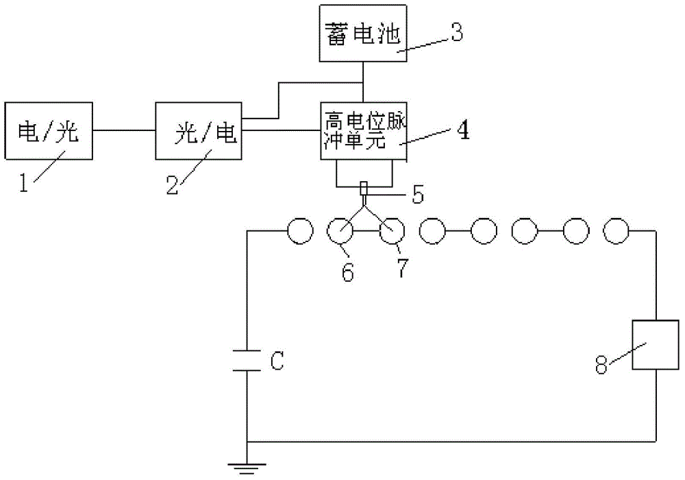
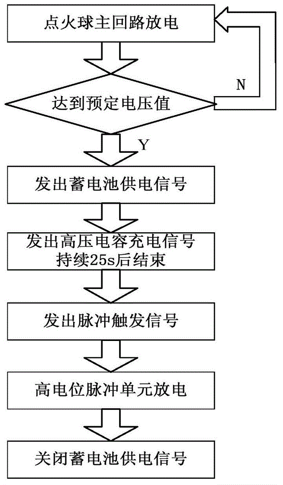
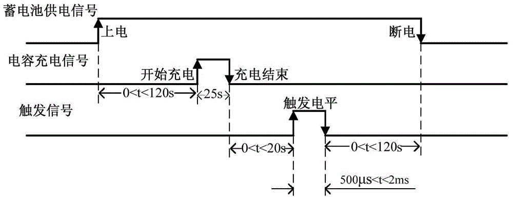
[0023] see Figure 1 to Figure 3 As shown, the present invention is a high-voltage electrical test trigger system using plasma jet technology, including an electro-optical converter 1, a photoelectric converter 2, a storage battery 3 and a high-potential pulse unit 4.

[0024] The electro-optic converter 1 includes a battery power supply signal input end, a high-voltage capacitor charging signal input end, a trigger electrical signal input end, a battery optical signal output end, a high-voltage capacitor charging optical signal output end, and a trigger optical signal output end; the photoelectric converter 2 includes a battery Optical signal input end, high voltage capacitor charging optical signal input end, trigger optical signal input end, battery power supply signal output end, high voltage capacitor charging signal output end and trigger electrical signal output end.

[0025] The battery light signal output terminal, the high-voltage capacitor charging light signal outp...


PUM


Abstract

The invention discloses a high-voltage electrical apparatus test triggering system and a method applying a plasma injection technology. The system comprises an electrical to optical converter, an optical to electrical converter, a storage battery and a high potential pulse unit, wherein an output end of the electrical to optical converter is connected with an input end of the optical to electrical converter; an output end of the optical to electrical converter is connected with the storage battery and the high potential pulse unit; and an output end of the high potential pulse unit is connected with an ignition head. The triggering system is developed based on a plasma injection principle; since an injection distance is long, a penetration success rate is high, and a triggering situation is stable; at the same time, the reliability of a triggering link in a high-voltage electrical apparatus test is ensured due to the advantage that a ball distance can be free from adjustment to the full extent, so that the test time is greatly saved; the test efficiency is effectively improved; the labor intensity of testing personnel is reduced at the same time; the situation of frequent entrance into a circuit for ball distance adjustment during a test or no penetration of triggering is avoided; and a potential safety hazard when the personnel enter the circuit is eliminated while the time is saved.

Description

【Technical field】 [0001] The invention belongs to the technical field of ultra-ultra-high-voltage electric appliance testing, and in particular relates to a high-voltage electric appliance test trigger system and method using plasma jet technology. 【Background technique】 [0002] Synthetic test is often used in UHV electrical tests, and the trigger system is an indispensable and important trigger device in the synthetic test. Whether the trigger system can be triggered correctly and in time, whether the distance between the trigger ball and the ball is appropriate, and the Whether the synthetic current can be successfully penetrated greatly affects the success rate of the synthetic test. The existing technology is to use a trigger ball with adjustable ball distance, and adjust the appropriate ball distance for different voltage level tests to determine the insulation and trigger distance. [0003] Although the existing trigger device has solved some of the technical problem...

Claims


Application Information

Patent Timeline
Patent Type & Authority Applications(China)
IPC IPC(8): G01R31/12
Inventor 姚斯立李刚姚远
Owner CHINA XD ELECTRIC CO LTD
Learn More