Eyepiece lens assembly and head-mounted optical system

An optical system and lens technology, which is applied in the field of eyepiece lenses and head-mounted optical systems, can solve the problems of users' neck fatigue, poor user experience, large pixel size, etc., and achieve the effects of eliminating chromatic aberration, low cost, and light weight

Active Publication Date: 2015-04-29
GOERTEK OPTICAL TECH CO LTD
View PDF4 Cites 45 Cited by
  • Summary
  • Abstract
  • Description
  • Claims
  • Application Information

AI Technical Summary

Problems solved by technology

The traditional solution is mostly a rotationally symmetrical eyepiece structure. Although the optical performance can be close to the diffraction limit and the distortion can be well corrected, the structure is complex, the assembly and processing require high precision, and the vol

Method used


Image

  • Eyepiece lens assembly and head-mounted optical system
  • Eyepiece lens assembly and head-mounted optical system
  • Eyepiece lens assembly and head-mounted optical system

Examples


Example Embodiment

[0033] In order to make the objectives, technical solutions, and advantages of the present invention clearer, the embodiments of the present invention will be described in further detail below in conjunction with the accompanying drawings.

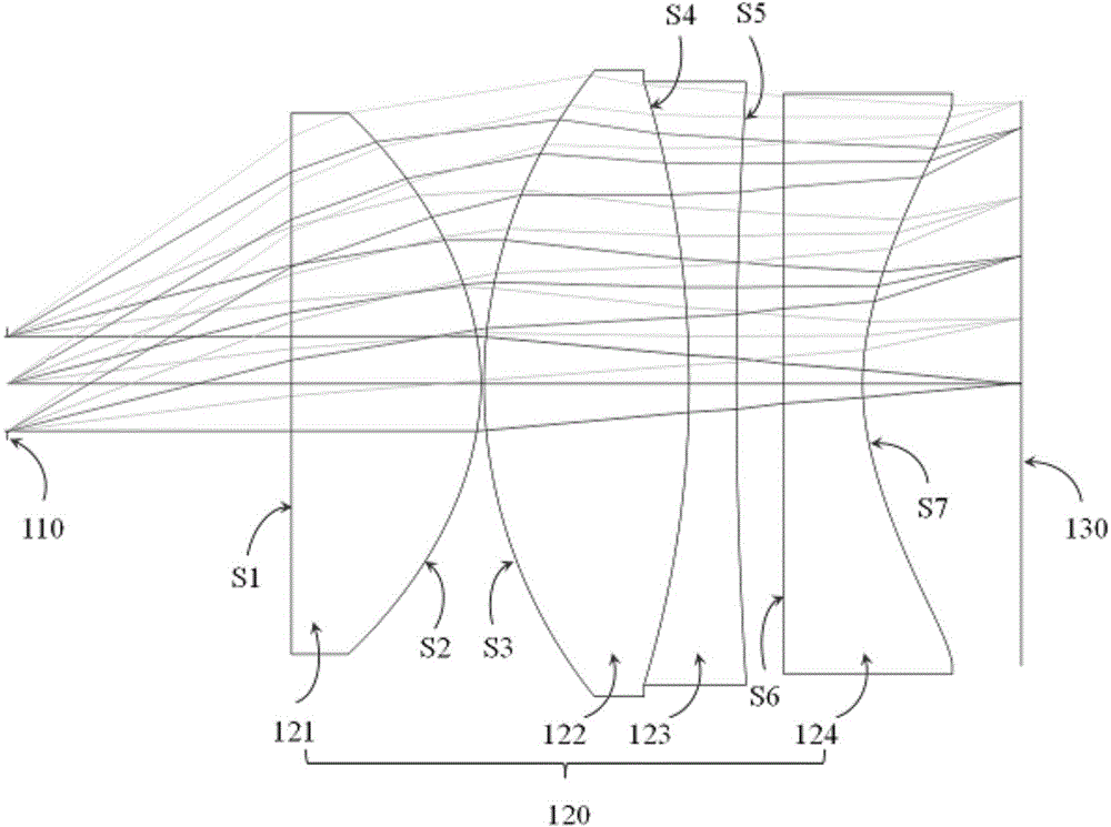
[0034] figure 1 A schematic diagram of a head-mounted optical system according to an embodiment of the present invention is shown. Such as figure 1 As shown, the head-mounted optical system adopts an inverted chasing light path design, and includes an aperture 110, an eyepiece lens 120, and a micro-display 130.

[0035] The eyepiece lens 120 includes four lenses, which are in turn against the incident direction of light:

[0036] The first positive lens 121 has a first surface S1 that is flat and a second surface S2 that is convex toward the light incident side; the second positive lens 122 has a third surface S3 that is convex toward the light emitting side and a third surface S3 that is convex toward the light incident side. The fourth surface...


PUM


Abstract

The invention discloses an eyepiece lens assembly and a head-mounted optical system. The eyepiece lens assembly comprises four lenses, namely, a first convex lens, a second convex lens, a third concave lens and a fourth concave lens, sequentially in the direction opposite to the light incidence direction, wherein the first convex lens comprises a first surface which is a plane as well as a second surface which is convex in the light incidence direction; the second convex lens comprises a third surface which is convex in the light outgoing direction as well as a fourth surface which is convex in the light incidence direction; the third concave lens comprises a fourth surface which is concave in the light outgoing direction as well as a fifth surface which is concave in the light incidence direction; the fourth concave lens comprises a sixth surface which is a plane as well as a seventh surface which is concave in the light incidence direction. The head-mounted optical system comprises a diaphragm, the eyepiece lens assembly and a micro display screen. The large-view-field, micro-display and high-image-quality head-mounted optical system is realized through reasonable configuration and model selection of the eyepiece lens assembly and the micro display screen, the viewing experience which is higher in quality and more comfortable is brought to a user, and the demand of the user is satisfied.

Description

technical field [0001] The invention relates to the field of lens design, in particular to an eyepiece lens and a head-mounted optical system. Background technique [0002] The head-mounted optical system is an image magnification system based on a micro-display. The image generated by the micro-display is magnified by the optical system, and an enlarged virtual image is presented at a certain distance in front of the person's eyes, so that the user can fully immerse in the virtual scene. without interference from external information. In many application fields, users of head-mounted optical systems work on the move, which requires the optical system to have a compact structure, light weight, and a large field of view on the basis of ensuring imaging quality. The traditional solution is mostly a rotationally symmetrical eyepiece structure. Although the optical performance can be close to the diffraction limit and the distortion can be well corrected, the structure is compl...

Claims


Application Information

Patent Timeline
IPC IPC(8): G02B25/00G02B27/01G02B27/00
CPCG02B25/001G02B27/0025G02B27/017G02B27/0172G02B2027/0116G02B2027/0123
Inventor 王元鹏杨春
Owner GOERTEK OPTICAL TECH CO LTD
Why Eureka
Try Eureka