Filter and neutron beam source
A technology of neutron beam and neutron, applied in the field of neutron beam source
- Summary
- Abstract
- Description
- Claims
- Application Information
AI Technical Summary
Problems solved by technology
Method used
Image
Examples
Embodiment 1
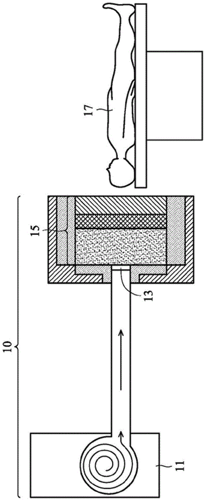
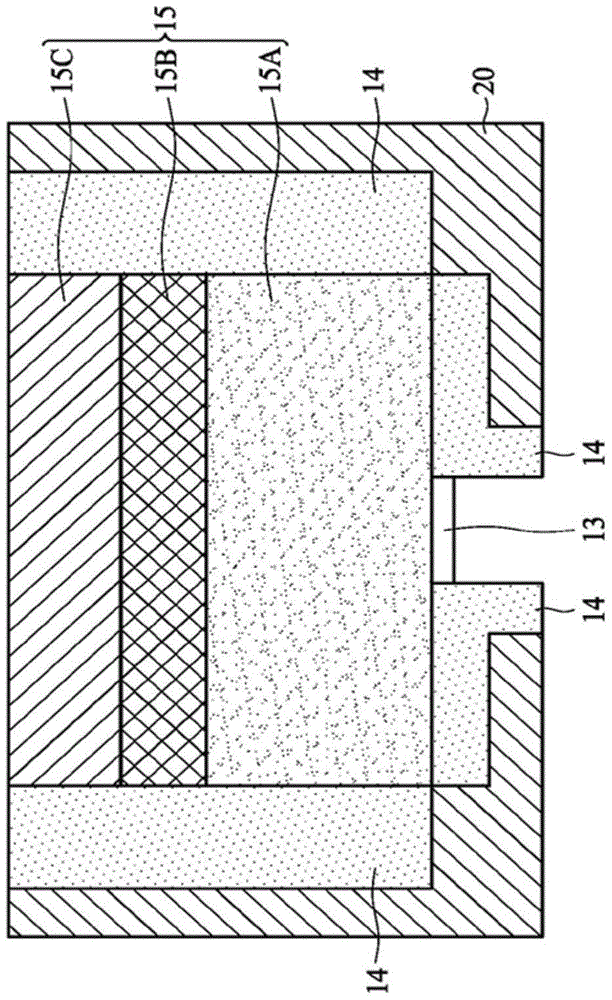
[0038] Take the first layer, the second layer, and the third layer of different thicknesses to form a circular cross-section (radius 50cm) screen. The epithermal neutron flux rate, fast neutron dose rate, and fast neutron dose accompanying each epithermal neutron produced by the neutron beam source containing the above filter screen are shown in Table 1:
[0039] Form 1
[0040]
[0041] From the comparison in Table 1, it can be seen that the aluminum atomic weight in the second layer is too large to effectively reduce the speed of fast neutrons, so it is necessary to increase the thickness of the second layer to reduce the dose of fast neutrons, but increasing the thickness of the second layer will also Reduced epithermal neutron flux rate. The smaller atomic weight of magnesium in the third layer can effectively reduce the speed of fast neutrons, but it also reduces the flux rate of epithermal neutrons. When the total thickness (embodiment 1-1) of the first layer and th...
Embodiment 2
[0043] Embodiment 2-1 is similar to Embodiment 1-5, the difference is that the second layer and the third layer are reversed. Although the epithermal neutron flux rate of Example 2-1 is higher, its fast neutron dose rate is also increased accordingly. In order to reduce the fast neutron dose rate in Example 2-1, it is necessary to increase the thickness of the third layer as in Example 2-2. However, although the fast neutron dose rate of embodiment 2-2 is close to the fast neutron dose of embodiment 1-5, its epithermal neutron flux rate is thus reduced. As can be seen from the above, the arrangement order of the first layer, the second layer, and the third layer in Embodiment 1-5 is better than that of the first layer, the third layer, and the second layer in Embodiment 2-1 and 2-2. Order.
[0044] Form 2
[0045]
Embodiment 3
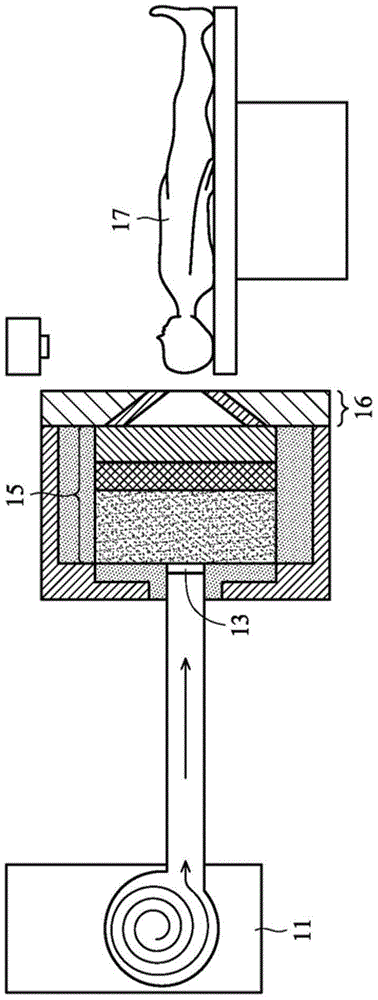
[0047] The thickness of the first layer is fixed at 30cm, and the second and third layers of different thicknesses are used to form a circular cross-section (50cm radius) filter screen, and Y-W H.Liu, T.T.Huang, S.H.Jiang, H.M.Liu are further matched , (2004) "Renovation of Epithermal Neutron Beam for BNCT at THOR," Appl. Radiat. Isot. 61, 1039-1043. Disclosed converging elements. The epithermal neutron flux rate, fast neutron dose rate, and fast neutron dose accompanying each epithermal neutron produced by the neutron beam source containing the above-mentioned filter screen and converging elements are shown in Table 3:
[0048] Form 3
[0049]
[0050] From the comparison of Table 3 with Table 1 and Table 2, it can be known that the converging element can maintain the intensity of the epithermal neutron flux rate and reduce the fast neutron dose rate.
PUM
| Property | Measurement | Unit |
|---|---|---|
| Total thickness | aaaaa | aaaaa |
| Section radius | aaaaa | aaaaa |
| Thickness | aaaaa | aaaaa |
Abstract
Description
Claims
Application Information
 - R&D
- Intellectual Property
- Life Sciences
- Materials
- Tech Scout
- Unparalleled Data Quality
- Higher Quality Content
- 60% Fewer Hallucinations
Browse by: Latest US Patents, China's latest patents, Technical Efficacy Thesaurus, Application Domain, Technology Topic, Popular Technical Reports.
© 2025 PatSnap. All rights reserved.Legal|Privacy policy|Modern Slavery Act Transparency Statement|Sitemap|About US| Contact US: help@patsnap.com


